


147
PARAMETERS
5
Monitor display and monitor output signal
5.12.2 Monitor display selection of the operation panel
(Pr. 52, Pr. 170, Pr. 171, Pr. 268, Pr. 563, Pr. 564)
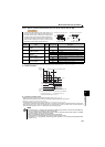
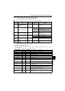
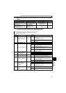
(1) Monitored item description list (Pr. 52)
Set the monitored item to be displayed on the operation panel and parameter unit (FR-PU04/FR-PU07) in Pr. 52 DU/PU
main display data selection.
Refer to the following table and set the monitored item to be displayed.
The monitor to be displayed on the main screen of the operation panel can be selected.
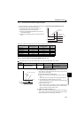
Parameter
Number
Name Initial Value Setting Range Description
52 ∗1
DU/PU main display data
selection
0
(output
frequency)
0, 5, 7 to 12, 14, 20,
23 to 25, 55, 61, 62,
100
∗2
Select the monitor to be displayed on the
operation panel.
Refer to the following table for monitor
description.
170 Watt-hour meter clear
9999
0 Set "0" to clear the watt-hour meter monitor.
10
Set the maximum value for the monitoring from
communication to 9999kWh.
9999
Set the maximum value for the monitoring from
communication to 65535kWh.
171 Operation hour meter clear
9999 0, 9999
Set "0" in the parameter to clear the operation
time monitor.
Setting 9999 does not clear.
268 ∗1
Monitor decimal digits
selection
9999
0 Displayed as integral value
1 Displayed in 0.1 increments.
9999 No function
563
Energization time carrying-
over times
0
0 to 65535
(reading only)
The numbers of cumulative energization time
monitor exceeded 65535h is displayed.
(Reading only)
564
Operating time carrying-
over times
0
0 to 65535
(reading only)
The numbers of operation time monitor
exceeded 65535h is displayed. (Reading only)
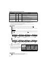
The above parameters can be set when Pr. 160 User group read selection = "0". (Refer to page 167)
∗1 This parameter allows its setting to be changed during operation in any operation mode even if "0" (initial value) is set in Pr. 77 Parameter write selection.
∗2 The setting values "56 and 57" are for manufacturer setting. Do not set.
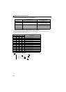
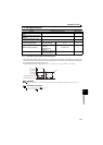
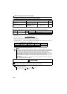
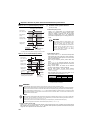
Monitored Item Unit Pr. 52 Setting Description
Output frequency 0.01Hz 0/100 Displays the inverter output frequency.
Output current 0.01A 0/100 Displays the inverter output current effective value.
Output voltage 0.1V 0/100 Displays the inverter output voltage.
Fault display — 0/100 Displays 8 past faults individually.
Frequency setting value 0.01Hz 5 Displays the set frequency.
Motor torque 0.1% 7
Displays the motor torque in % on the assumption that the rated motor torque
is 100%. (Displays 0% during V/F control)
Converter output voltage 0.1V 8 Displays the DC bus voltage value.
Regenerative brake duty 0.1% 9 Brake duty set in Pr. 30, Pr. 70
Electronic thermal relay
function load factor
0.1% 10
Displays the thermal cumulative value on the assumption that the thermal
operation level is 100% (Larger thermal between the motor thermal and
transistor thermal). ∗4
Output current peak value 0.01A 11
Holds and displays the peak value of the output power monitor.
(Cleared at every start)
Converter output voltage
peak value
0.1V 12
Holds and displays the peak value of the DC bus voltage value.
(Cleared at every start)
Output power 0.01kW 14 Displays the power on the inverter output side
Cumulative energization time
∗1
1h 20
Adds up and displays the energization time after inverter shipment.
You can check the numbers of the monitor value exceeded 65535h with Pr. 563.
Actual operation time ∗1, ∗2 1h 23
Adds up and displays the inverter operation time.
You can check the numbers of the monitor value exceeded 65535h with Pr. 564.
Can be cleared by Pr. 171. (Refer to page 149)
Motor load factor 0.1% 24
Displays the output current value on the assumption that the inverter rated
current value is 100%.
Monitor value = output power monitor value/rated inverter current 100 [%]