


148
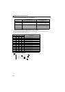
Monitor display and monitor output signal
∗1 The cumulative energization time and actual operation time are accumulated from 0 to 65535 hours, then cleared, and accumulated again from 0.
When the operation panel is used, the time is displayed up to 65.53 (65530h) in the indication of 1h = 0.001, and thereafter, it is added up from 0.
∗2 Actual operation time is not accumulated when the cumulative operation time is less than 1h until turning OFF of the power supply.
∗3 Since the panel display of the operation panel is 4 digits in length, the monitor value of more than "9999" is displayed "----".
∗4 Larger thermal value between the motor thermal and transistor thermal is displayed.
A value other than 0% is displayed if the surrounding air temperature (heatsink temperature) is high even when the inverter is at a stop.
∗5 The unit is 1kWh when monitoring through FL remote communication.
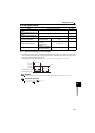
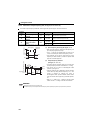
∗ The set frequency displayed indicates the frequency to be output when the start
command is ON. Different from the frequency setting displayed when Pr. 52 = "5",
the value based on maximum/minimum frequency and frequency jump is displayed.
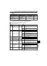
Cumulative power ∗3
0.01kWh
∗5 25
Adds up and displays the power amount based on the output power monitor.
Can be cleared by Pr. 170. (Refer to page 149)
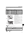
Inverter output terminal
monitor
—55
Displays the ON/OFF statuses of the inverter output terminals and FL remote
communication virtual terminals (FU, ALM signal) on the operation panel.
(Refer to page 149 for details)
Motor thermal load factor 0.1% 61
Motor thermal heat cumulative value is displayed.
(Motor overload trip (E.THM) at 100%)
Inverter thermal load factor 0.1% 62
Transistor thermal heat cumulative value is displayed.
(Inverter overload trip (E.THT) at 100%)
Cumulative power 2 0.01kWh —
Adds up and displays the power amount based on the output power monitor.
(dedicated monitor for FL remote communication)
Can be cleared by Pr. 170. (Refer to page 149)
REMARKS
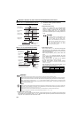
By setting "0" in Pr. 52, the monitoring of output speed to fault display can be selected in sequence by .
When the operation panel is used, the displayed units are Hz and A only and the others are not displayed.
The monitor set in Pr. 52 is displayed in the third monitor position. However, change the output current monitor for the motor
load factor.
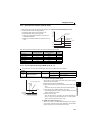
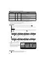
∗The monitor displayed at powering on is the first monitor. Display the monitor you want to display on the first monitor and hold
down for 1s. (To return to the output frequency monitor, hold down for 1s after displaying the output frequency
monitor.)
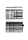
Example)When Pr. 52 is set to "20" (cumulative energization time), the monitor is displayed on the operation panel as described
below.
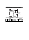
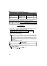
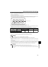
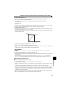
(2) Display set frequency during stop
(Pr. 52)
When "100" is set in Pr. 52, the set frequency
and output frequency are displayed during stop
and operation respectively. (LED of Hz flickers
during stop and is lit during operation.)
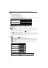
Pr. 52
0 100
During
running/stop
During stop
During
running
Output frequency
Output
frequency
Set
frequency∗
Output
frequency
Output current Output current
Output voltage Output voltage
Fault display Fault display
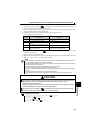
REMARKS
During an error, the output frequency at error occurrence appears.
During MRS signal is ON, the values displayed are the same as during a stop.
During offline auto tuning, the tuning status monitor has priority.
Monitored Item Unit Pr. 52 Setting Description
Initial Value
With fault
Output current monitor
Output voltage monitor
Output frequency monitor
Power-on monitor (first monitor) Second monitor Third monitor Fault monitor
With fault
Output current monitor
Cumulative energization time monitor
Output frequency monitor
Power-on monitor (first monitor) Second monitor Third monitor Fault monitor