


25
Connection of stand-alone option unit
2
WIRING
2.4 Connection of stand-alone option unit
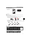
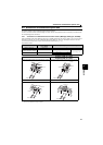
The inverter accepts a variety of stand-alone option units as required.
Incorrect connection will cause inverter damage or accident. Connect and operate the option unit carefully in accordance with
the corresponding option unit manual.
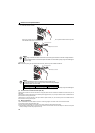
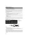
2.4.1 Connection of a dedicated external brake resistor (MRS type, MYS type, FR-ABR)
Install a dedicated brake resistor (MRS type, MYS type, FR-ABR) outside when the motor is made to run by the load, quick
deceleration is required, etc. Connect a dedicated brake resistor (MRS type, MYS type, FR-ABR) to terminal P/+ and PR.
(For the locations of terminal P/+ and PR, refer to the terminal block layout (page 15).)
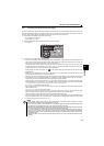
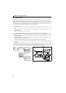
Set parameters below.
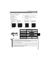
∗1 Do not remove the jumper across terminals P/+ and P1 except when connecting a DC reactor.
∗2 The shape of jumper differs according to capacities.
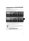
Connected Brake Resistor
Pr. 30 Regenerative function
selection Setting
Pr. 70 Special regenerative brake duty Setting
MRS type, MYS type 0 (initial value) —
MYS type
(used at 100% torque / 6%ED)
16%
Refer to page 136
FR-ABR 1
7.5K or lower 10%
11K or higher 6%
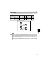
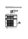
FR-E720-0.4KNF, 0.75KNF
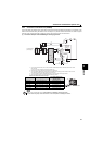
FR-E720-1.5KNF to 3.7KNF
FR-E740-0.4KNF to 3.7KNF
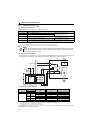
Connect the brake resistor across terminals P/+ and PR. Connect the brake resistor across terminals P/+ and PR.
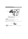
FR-E720-5.5KNF to 15KNF FR-E740-5.5KNF to 15KNF
Connect the brake resistor across terminals P/+ and PR. Connect the brake resistor across terminals P/+ and PR.
Terminal PR
Brake resistor
Jumper
*1
Terminal P/+
Terminal P/+
Brake resistor
Jumper
*1
Terminal PR
Brake resistor
Terminal P
R
Terminal P/+
Jumper
*1
Terminal PR
Brake resistor
Jumper
*1*2
Terminal P/+