


180
Useful functions
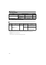
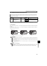
(5) Cooling fan life display
The cooling fan speed of 50% or less is detected, and "FN" is displayed on the operation panel. As an alarm display, Pr.
255 bit2 is turned ON.
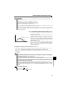
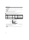
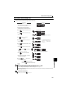
5.19.3 Maintenance timer alarm (Pr. 503, Pr. 504)
The cumulative energization time of the inverter is stored into the EEPROM every hour and is displayed in Pr. 503
Maintenance timer in 100h increments. Pr. 503 is clamped at 9998 (999800h).
When the Pr. 503 value reaches the time set to Pr. 504 Maintenance timer alarm output set time (100h increments), the
maintenance timer alarm output signal (Y95) is output.
REMARKS
When the inverter is mounted with two or more cooling fans, "FN" is displayed with one or more fans with speed of 50% or less.
NOTE
For replacement of each part, contact the nearest Mitsubishi FA center.
Maintenance timer signal (Y95) is output when the inverter's cumulative energization time reaches the time period set
by the parameter during FL remote communication. (MT) is displayed on the operation panel.
This can be used as a guideline for the maintenance time for peripheral devices.
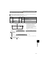
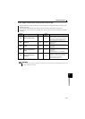
Parameter
Number
Name Initial Value Setting Range Description
503 Maintenance timer
0 0 (1 to 9998)
Displays the cumulative energization time
of the inverter in 100h increments.
(Reading only)
Writing the setting of "0" clears the
cumulative energization time.
504
Maintenance timer alarm
output set time
9999
0 to 9998
Time taken until when the maintenance
timer alarm output signal (Y95) is output.
9999 No function
The above parameters can be set when Pr. 160 User group read selection = "0". (Refer to page 167)
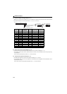
NOTE
The cumulative energization time is counted every hour. The energization time of less than 1h is not counted.
First power
Time
ON
Maintenance
timer
(Pr. 503)
Set "0" in Pr. 503
Y95 signal
MT display
OFF ONON
Pr. 504
9998
(999800h)