


51
4
FL REMOTE COMMUNICATION FUNCTION
Operation mode setting
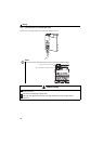
4.5.2 PU operation interlock
The PU operation interlock function is designed to forcibly change the operation mode to the Network operation mode
when the PU operation interlock signal (X12) input turns OFF.
This function prevents the operation mode from being accidentally unswitched from the PU operation mode. If the
operation mode is left unswitched from the PU operation mode, the inverter does not reply to the commands sent through
FL remote communication.
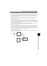
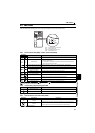
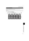
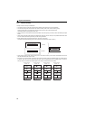
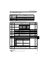
<Function/operation changed by switching ON-OFF the X12 signal>
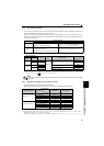
4.5.3 Operation availability in each operation mode
Operation availability in each operation mode is shown below.
(Monitoring and parameter read can be performed from any operation regardless of operation mode.)
∗1 Some parameters may be write-disabled according to the Pr. 77 Parameter write selection setting and operating status. (Refer to page 166)
∗2 Some parameters are write-enabled independently of the operation mode and command source presence/absence. When Pr. 77 = 2, write is enabled.
(Refer to the parameter list on page 78) Parameter clear is disabled.
∗3 Enabled only when stopped by the PU. At a PU stop, PS is displayed on the operation panel. As set in Pr. 75 Reset selection/PU stop selection. (Refer to page 165)
X12 Signal
Function/Operation
Operation mode Parameter write
ON
Operation mode (PU, NET) switching enabled
Output stop during Network operation
Parameter write is enabled (depending on Pr. 77
Parameter write selection and each parameter write
conditions (Refer to page 78 for the parameter list))
OFF
Forcibly switched to Network operation mode
Network operation allowed
Switching between the PU operation mode is enabled
Parameter write is disabled
(Note that the Pr.297 setting is available when Pr.296 ≠
"9999.")
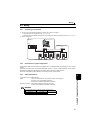
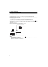
Operating Condition
X12 Signal
Operation
Mode
Operating Status
Switching to PU
Operation Mode
Operation
mode
Status
PU
During stop ON OFF ∗1
Network ∗2
If Network operation frequency setting and start
signal are entered, operation is performed in that
status.
Disallowed
Running ON OFF ∗1 Disallowed
Network
During stop
OFF ON
During stop
Allowed
ON OFF Disallowed
Running
OFF ON During operation output stop Disallowed
ON OFF Output stop operation Disallowed
∗1 The operation mode switches to the Network operation mode independently of whether the start signal (STF, STR) is ON or OFF. Therefore, the
motor is run in Network operation mode when the X12 signal is turned OFF with either of STF and STR ON.
∗2 At fault occurrence, pressing of the operation panel resets the inverter.
NOTE
If the X12 signal is ON, the operation mode cannot be switched to the PU operation mode when the start signal (STF,
STR) is ON.
Operation Location
Operation Mode
Item
PU Operation NET Operation
Operation panel
Run command (start) ×
Run command (stop) Δ ∗3
Running frequency setting ×
Parameter write ∗1 × ∗2
Inverter reset ×
FL remote communication
Run command (start) ×
Run command (stop) ×
Running frequency setting ×
Parameter write × ∗2 ∗1
Inverter reset ×
: Enabled, ×: Disabled, Δ: Some are enabled