


94
Adjustment of the output torque (current) of the motor
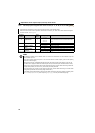
5.4 Adjustment of the output torque (current) of the motor
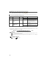
5.4.1 Manual torque boost (Pr. 0, Pr. 46)
(1) Starting torque adjustment
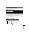
On the assumption that Pr. 19 Base frequency voltage is 100%, set
the output voltage at 0Hz in % to Pr. 0 (Pr. 46).
Adjust the parameter little by little (about 0.5%), and check the
motor status each time. If the setting is too large, the motor will
overheat. The guideline is about 10% at the greatest.
(2) Set two kinds of torque boosts (RT signal, Pr. 46)
When you want to change torque boost according to applications, switch multiple motors with one inverter, etc., use Second
torque boost.
Pr. 46 Second torque boost is valid when the RT signal is ON.
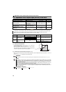
Purpose Parameter that should be Set Refer to Page
Set starting torque manually Manual torque boost Pr. 0, Pr. 46
94
Automatically control output current
according to load
Advanced magnetic flux vector
control,
General-purpose magnetic flux
vector control
Pr. 71, Pr. 80, Pr. 81, Pr. 89,
Pr. 90, Pr. 450, Pr. 800
95, 98
Compensate for motor slip to secure
low-speed torque
Slip compensation (V/F control
and General-purpose magnetic
flux vector control only)
Pr. 245 to Pr. 247
100
Limit output current to prevent
inverter trip
Stall prevention operation
Pr. 22, Pr. 23, Pr. 66, Pr. 156,
Pr. 157
101
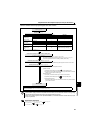
A voltage drop in the low-frequency range can be compensated to improve motor torque reduction in the low-speed range.
Motor torque in the low-frequency range can be adjusted to the load to increase the starting motor torque.
Turning the RT signal ON/OFF switches between two start torque boost settings.
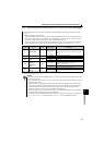
Parameter
Number
Name Initial Value
Setting
Range
Description
0 Torque boost
0.1K to 0.75K 6%
0 to 30% Set the output voltage at 0Hz as %.
1.5K to 3.7K 4%
5.5K, 7.5K 3%
11K, 15K 2%
46 ∗
Second torque
boost
9999
0 to 30%
Set the torque boost when the RT
signal is ON.
9999 Without second torque boost
∗ The above parameters can be set when Pr. 160 User group read selection = "0". (Refer to page 167)
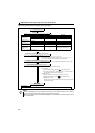
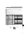
REMARKS
The RT signal acts as the second function selection signal and makes the other second functions valid. (Refer to page 143)
NOTE
y The amount of current flows in the motor may become large according to the conditions such as the motor
characteristics, load, acceleration/deceleration time, wiring length, etc., resulting in an overcurrent trip (OL
(overcurrent alarm) then E.OC1 (overcurrent trip during acceleration), overload trip (E.THM (motor overload trip), or
E.THT (inverter overload trip).
(When a fault occurs, release the start command, and decrease the Pr. 0 setting 1% by 1% to reset.) (Refer to page 192.)
y The Pr. 0, Pr. 46 settings are valid only when V/F control is selected.
y When using the inverter dedicated motor (constant-torque motor) with the
5.5K, 7.5K
, set torque boost value to 2%.
When Pr. 0 = "3%"(initial value), if Pr. 71 value is changed to the setting for use with a constant-torque motor, the Pr. 0
setting changes to 2%.
Parameters referred to
Pr. 3 Base frequency, Pr. 19 Base frequency voltage Refer to page 107
Pr. 71 Applied motor Refer to page 125
V/F
V/F
V/F
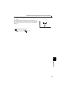
Output voltage
P
r. 0
P
r. 46
Setting range
Base frequenc
y
0
100%
Output frequency (Hz)