


24
Control circuit specifications
2.3.4 Safety stop function
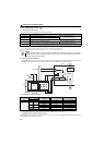
(1) Description of the function
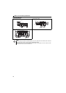
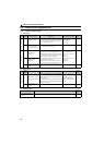
The terminals related to the safety stop function are shown below.
∗1 In the initial status, terminal S1 and S2 are shorted with terminal PC by shortening wire. Remove the shortening wire and connect the safety relay module
when using the safety stop function.
∗2 At an internal safety circuit failure, one of E.SAF, E.6, E.7, and E.CPU is displayed on the operation panel.
......Specifications differ according to the date assembled. Refer to page 232 to check the SERIAL number.
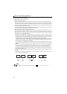
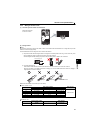
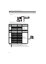
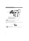
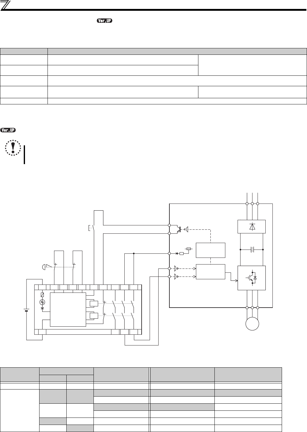
(2) Wiring connection diagram
To prevent restart at fault occurrence, connect terminals Y0 (SAFE2 signal) and SE to terminals XS0 and XS1, which are
the feedback input terminals of the safety relay module. Terminal Y0 is turned OFF at a fault occurrence.
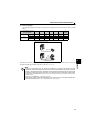
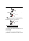
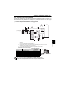
(3) Safety stop function operation
∗1 At an internal safety circuit failure, one of E.SAF, E.6, E.7, and E.CPU is displayed on the operation panel.
∗2 SA is displayed when both of the S1 and S2 signals are in open status and no internal safety circuit failure exists.
∗3 ON: Transistor used for an open collector output is conducted.
OFF: Transistor used for an open collector output is not conducted.
For more details, refer to the Safety stop function instruction manual (BCN-A211508-004). (Refer to the front cover of the Instruction
Manual (Basic) for how to obtain the manual.)
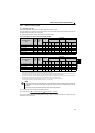
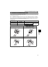
Terminal Symbol Description
S1∗1 For input of safety stop channel 1.
Between S1 and PC / S2 and PC
Open: In safety stop state.
Short: Other than safety stop state.
S2
∗1 For input of safety stop channel 2.
PC
∗1 Common terminal for terminal S1 and S2.
Y0 (SAFE2 signal)
Outputs when an alarm or failure is detected.
The signal is output when no internal safety circuit failure
∗2 exists.
OFF: Internal safety circuit failure.
∗2
ON : No internal safety circuit failure.∗2
SE Common terminal for open collector outputs (terminal Y0)
NOTE
y
Hold the ON or OFF status for 2ms or longer to input signal to terminal S1 or S2. Signal input shorter than 2ms is not recognized.
y SAFE2 signal can only be used to output an alarm or to prevent restart of an inverter. The signal cannot be used as
safety stop input signal to other devices.
Input power
Input signal
Internal safety
circuit∗1
Output signal (SAFE2)∗3 Operation state
S1-PC S2-PC
O FF ----- ----- ----- O FF O utp ut s hu tof f (S af e s ta te )
ON
Short Short
No failure ON Drive enabled
Detected OFF Output shutoff (Safe state)
Open Open
No failure∗2 ON Output shutoff (Safe state)
Detected OFF Output shutoff (Safe state)
Short Open Detected OFF Output shutoff (Safe state)
Open
Short Detected OFF Output shutoff (Safe state)
S2
S1
START/RESET
+24V
K1
K2
DC24V
Y0(SAFE2)
R S T
U V W
IM
SE
PC
MITSUBISHI MELSEC Safety relay module
QS90SR2SN-Q
Internal
Safety
Circuit
Emergency
stop button
Inverter
I/O control
Output shutoff
circuit
X0 X1
COM0
COM1
24G
XS0
XS1
Z10
Z00
Z20
Z11 Z01 Z21