


46
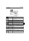
FL remote communication specification
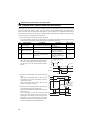
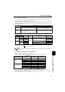
4.1 FL remote communication specification
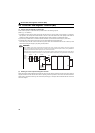
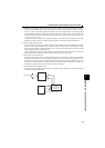
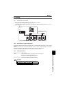
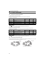
4.2 Node address setting
Set the node address between "1 to 64" using node address switches. (Refer to page 2) The setting is applied when the power
turns OFF once, then ON again.
Set the arrow () of the corresponding switches to the number to set a desired address.
Setting example
Type
Built-in to an inverter, RJ-45 connector connection method
Power supply
Supplied from the inverter or the 24V external power supply
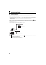
Connection cable
FL-net dedicated cable (Refer to page 47)
Maximum number of
connectable inverters
64 units maximum
Communication speed
Auto negotiation (auto detection) (10Mbps/100Mbps)
Topology
y Star (connection with a hub in the center)
y Star bus (connection with multiple hubs)
Communication
distance
y Between node ⇔ hub: 100m maximum (Node indicate master and inverters.)
y Between hubs: 100m maximum
y Overall length: 2000m maximum
Electrical interface
Conforms to IEEE802.3u (conforms to CSMA/CD)
Transmission protocol
FL remote
Node address setting
Can be set with node address switch. (Refer to page 46)
Reflected to IP address as well. (192.168.250. node address)
I/O points
Input 64 points, output 64 points
Node address 1:
Set the "
" of X10(SW2) to "0" and the
"
" of X1(SW1) to "1."
Node address 26:
Set the "
" of X10(SW2) to "2" and the
"
" of X1(SW1) to "6."
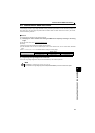
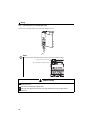
NOTE
y Always remove the front cover before setting a node address with node address switches.
(Refer to page 5 for how to remove the front cover.)
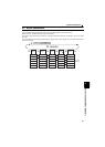
y
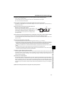
Set the node address switch to the switch number position correctly. If the switch is set
between numbers, normal data communication can not be established.
y If the node address switch is set to a value other than "1 to 64", it is invalid due to outside of setting range. In this
case, DEV LED is lit red and E.OPT appears on the operation panel. (Refer to page 209)
y You cannot set the same node address to other devices on the network. (Doing so disables proper communication.)
y
Set the inverter node address before switching ON the inverter and do not change the setting while power is
ON. Otherwise you may get an electric shock.
0
9
8
7
6
5
4
3
2
1
0
9
8
7
6
5
4
3
2
1
X1
X10
0
9
8
7
6
5
4
3
2
1
0
9
8
7
6
5
4
3
2
1
X1
X10
0
9
8
7
6
5
4
3
2
1
0
9
8
7
6
5
4
3
2
1
Good
example
Bad
example