


145
PARAMETERS
5
I/O signal control
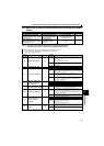
5.11.6 Output current detection function (Y12 signal, Y13 signal, Pr. 150 to Pr. 153)
The above parameters can be set when Pr. 160 User group read selection = "0". (Refer to page 167)
The output current is detected while the inverter is running, and the signals are output through FL remote
communication.
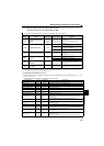
Parameter
Number
Name Initial Value
Setting
Range
Description
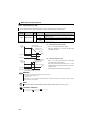
150
Output current detection
level
150% 0 to 200% 100% is the rated inverter current.
151
Output current detection
signal delay time
0s 0 to 10s
Output current detection period.
The time from when the output current has risen
above the setting until the output current detection
signal (Y12) is output.
152
Zero current detection
level
5% 0 to 200%
The rated inverter current is assumed to be 100%.
153
Zero current detection
time
0.5s 0 to 1s
Period from when the output current drops below the
Pr. 152
value until the zero current detection signal
(Y13) is output.
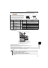
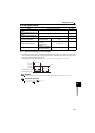
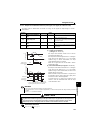
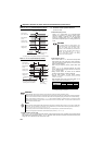
(1) Output current detection
(Y12 signal, Pr. 150, Pr. 151)
The output current detection function can be used for
excessive torque detection, etc.
If the output current remains higher than the Pr.150 setting for
longer than the time period set in Pr.151 in the inverter
operation using FL remote communication, the output
current detection signal (Y12) is output.
When the Y12 signal turns ON, the ON state is held for
approximately 100ms.
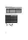
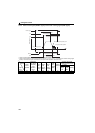
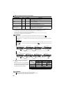
(2) Zero current detection (Y13 signal, Pr. 152, Pr. 153)
If the output current remains lower than the Pr.152 setting for
longer than the time period set in Pr.153 in the inverter
operation using FL remote communication, the zero current
detection signal (Y13) is output.
When the inverter's output current falls to "0", torque will not
be generated. This may cause a drop due to gravity when
the inverter is used in vertical lift application.
To prevent this, the Y13 signal can be output from the
inverter to close the mechanical brake when the output
current has fallen to "zero".
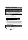
REMARKS
This function is also valid during execution of the offline auto tuning.
The response time of Y12 and Y13 signals is approximately 0.1s. Note that the response time changes according to the load
condition.
When Pr. 152 = "0", detection is disabled.
CAUTION
The zero current detection level setting should not be too low, and the zero current detection time setting not too
long. Otherwise, the detection signal may not be output when torque is not generated at a low output current.
To prevent the machine and equipment from resulting in hazardous conditions detection signal, install a
safety backup such as an emergency brake even the zero current detection function is set valid.
Parameters referred to
Offline auto tuning Refer to page 127
Time
Pr. 150
OFF
ON
OFF
Output current
detection signal
(Y12)
100ms
Output current
Pr. 151
OFF ON
Start signal
Time
Output current
OFF
ON
Zero current
detection time
(Y13)
Pr. 153
Detection time
Pr. 153
Detection time
Pr. 152
OFF
ON
0[A]
100ms*
Pr. 152
∗ The zero current detection signal (Y13) holds the
signal for approximately 100ms once turned ON.