


49
4
FL REMOTE COMMUNICATION FUNCTION
LED status
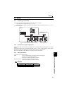
4.4 LED status
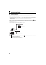
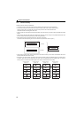
Each LED indicates the operating status of the inverter and network according to the indication status.
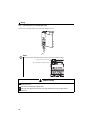
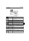
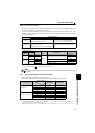
4.4.1 Device status LED (DEV), remote status LED (RMT)
:OFF, : red is lit, : green is lit, :red is flickering, : green is flickering,
: red and green are alternately flickering
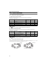
4.4.2 Transmitting (TX)/receiving (RX) LED
:OFF, : green is lit
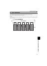
4.4.3 Communication set status LED (CHG)
:OFF, : red is flickering
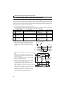
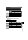
LED Status
Node Status Description
DEV RMT
Power is OFF The inverter power is OFF.
Hardware fault
y Node address is out of range (other than 1 to 64).
y The option board is faulty.
y A contact fault or other failure has occurred in the option connector between the
inverter and a communication option.
FL remote network is not connected
Although hardware is normal, it is not connected to the FL remote network.
FL remote network at a remote stop
It is correctly set to connect to the FL remote network and waiting for remote I/O control.
FL remote network during remote
connection processing
Although remote I/O control started, initial processing is in progress.
Master is not present When the master is disconnected from FL remote network.
FL remote network
during remote operation
During remote I/O control
Own node is disconnected When the own node is disconnected from FL remote network.
Setting error
Although it is connected to the FL remote, setting error is found.
(When the slave is not the one the master is expected.)
Duplicate node When node address is duplicate with other node address
Unsupported protocol Communication is attempted via an unsupported protocol.
LED Status Node Status Description
Not transmitting (TX)
/not receiving (RX)
Transmitting (TX)/receiving (RX) Flickers at high speed during continuous transmitting/receiving
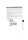
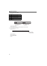
LED Status Node Status Description
Communication setting is not
changed
Communication setting is
changed
Red flickers when the setting value actually reflected and of node address switch
differ. The setting value of the node address switch is reflected by re-powering ON the
inverter in this status, then communication setting status LED turns OFF.
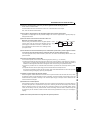
CHG
TX RX
DEV
RMT
CHG
DEV
TX/RX
RMT
: Communication set status LED
: Device status LED
: Reception/transmission LED
: Remote status LED