


59
4
FL REMOTE COMMUNICATION FUNCTION
Cyclic transmission
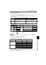
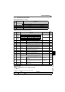
4.7.3 Input data (inverter to master)
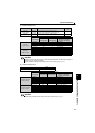
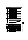
[Master input area (inverter → master)]
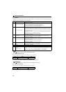
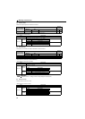
(1) Inverter status monitor
Monitors the output signal of the inverter from the network.
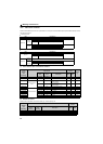
(2) Alarm code
Description of an alarm that occurred in the inverter can be read.
Word
Address
(word boundary)
(n: node address)
Applications
Bit 15 14 13 12 11 10 9 8 7 6 5 4 3 2 1 0
0 4(n-1)+0 (1) Inverter status monitor
1 4(n-1)+1 (3) Life/alarm (2) Alarm code
2 4(n-1)+2 (4) Output frequency monitor
3 4(n-1)+3 (5) Output current monitor
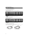
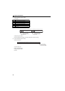
Bit Signal Description Related Parameters
Refer
to
Page
0
During
forward
rotation
——
1
During
reverse
rotation
——
2 RUN signal Inverter running
When the inverter output frequency reaches or exceeds
Pr.13 Starting frequency, the value changes to "1".
—
142
3 SU signal
Reached the
frequency
When the output frequency reaches the set frequency, the
value changes to "1".
Pr.41 144
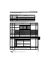
4 — (not used) Always 0 ——
5 OL signal Overload alarm
While stall prevention function is activated, the value
changes to "1".
Pr.22, Pr.23, Pr.66 101
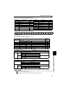
6 FU signal
Output frequency
detection
When the output frequency reaches the frequency set in
Pr. 42
(
Pr. 43
for reverse rotation), the value changes to "1".
Pr.42, Pr.43 144
7 ALM signal Fault
When the inverter protective function is activated to stop
the output (fault), the value changes to "1".
— 192
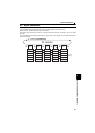
8 — (not used) Always 0 ——
9
Safety alarm
signal
Internal safety circuit
fault
When an internal safety circuit fault (E.SAF, E. 6, E. 7, or
E.CPU) occurs, the value changes to "1".
——
10 Edit signal Edit enabled
0: Parameter change disabled (X12 signal = "0")
1: Parameter change enabled (X12 signal = "1")
——
11 NET signal
0: Command (run command/speed command) can not be given through network
1: Command (run command/speed command) can be given through network
——
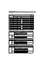
12 Y12 signal
Output current
detection
When the output current is higher than the Pr.150 setting
and persists for longer than the time set in Pr.151, the value
changes to "1".
Pr.150, Pr.151 145
13 Y13 signal
Zero current
detection
When the output current is lower than the Pr.152 setting and
persists for longer than the time set in Pr.153, the value
changes to "1".
Pr.152, Pr.153 145
14
READY
signal
Reset cancel
0: inverter resetting/starting after power is turned on
1: Reset canceling
— 142
15 — (not used) Always 0 ——
REMARKS
y The values of each bit, "0" and "1," indicate "OFF" and "ON."
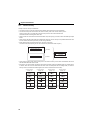
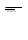
Bit Name Description
0 to 7 Alarm code When an alarm (fault) occurs in the inverter, fault code is displayed. (Refer to page 67)
Bit0 Bit1 Operation
Forward rotation: 0 Reverse rotation: 0 During stop
Forward rotation: 1 Reverse rotation: 0 During forward rotation
Forward rotation: 0 Reverse rotation: 1 During reverse rotation
Forward rotation: 1 Reverse rotation: 1 Not used