


143
PARAMETERS
5
I/O signal control
5.11.3 Second function selection signal (RT signal)
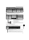
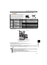
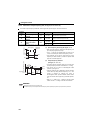
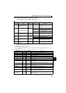
When the RT signal is ON, the following second functions are selected at the same time.
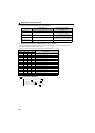
5.11.4 Inverter output shutoff signal (MRS signal, Pr. 17)
When the RT signal turns ON, the second function becomes valid.
The second function has the following applications.
(a) Switching between normal use and emergency use
(b) Switching between heavy load and light load
(c) Changing of acceleration/deceleration time by broken line
acceleration/deceleration
(d) Switching of characteristic between the main motor and sub
motor
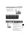
Second acceleration/deceleration time
Function
First Function
Parameter Number
Second Function
Parameter Number
Refer to
Page
Torque boost Pr. 0 Pr. 46 94
Base frequency Pr. 3 Pr. 47 107
Acceleration time Pr. 7 Pr. 44 116
Deceleration time Pr. 8 Pr. 44, Pr. 45 116
Electronic thermal O/L relay Pr. 9 Pr. 51 123
Stall prevention Pr. 22 Pr. 48 101
Applied motor Pr. 71 Pr. 450 125
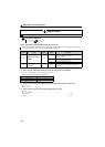
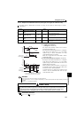
The inverter output can be shut off by the MRS signal. Also, logic for the MRS signal can be selected.
Parameter
Number
Name Initial Value Setting Range Description
17 MRS input selection
0
0, 4 Normally open input
2
Normally closed input
(NC contact input specifications)
The above parameters can be set when Pr. 160 User group read selection = "0". (Refer to page 167)
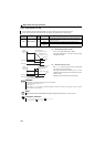
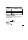
(1) Output shutoff signal (MRS signal)
Turning ON the output shutoff signal (MRS) during inverter running
shuts off the output immediately.
MRS signal may be used as described below.
(a) When mechanical brake (e.g. electromagnetic brake) is used to stop
motor
The inverter output is shut off when the mechanical brake operates.
(b) To provide interlock to disable operation by the inverter
With the MRS signal ON, the inverter cannot be operated if the start
signal is entered into the inverter.
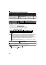
(c) Coast the motor to a stop.
When the start signal is turned OFF, the inverter decelerates the
motor to a stop in the preset deceleration time, but when the MRS
signal is turned ON, the motor coasts to a stop.
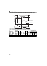
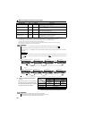
(2) MRS signal logic inversion (Pr. 17)
When Pr. 17 is set to "2", the MRS signal (output stop) can be changed
to the normally closed (NC contact) input specification. When the MRS
signal turns ON (opens), the inverter shuts off the output.
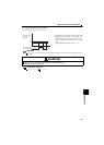
RT
Output frequency
Acceleration time
is reflected
Time
RH
RM
ON
ON
MRS Signal
Time
STF (STR)
signal
The motor coasts to stop