


57
4
FL REMOTE COMMUNICATION FUNCTION
Cyclic transmission
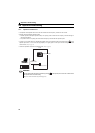
4.7.2 Output data (master to inverter)
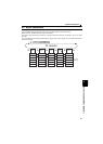
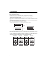
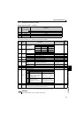
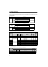
[Master output area (master → inverter)]
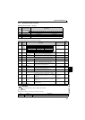
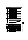
(1) Control input command
Set control input command such as forward and reverse rotation commands.
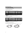
∗1 When Pr. 59 Remote function selection = "1" or "2", the functions of the RL, RM and RH signals are changed as given in the table.
∗2 When Pr. 270 Stop-on contact control selection = "1", functions of RL and RT signals are changed as in the table.
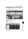
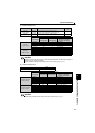
Word
Address
(word boundary)
(n: node address)
Applications
Bit 15 14 13 12 11 10 9 8 7 6 5 4 3 2 1 0
0 4(n-1)+256 (1) Control input command
1 4(n-1)+257 — (not used)
2 4(n-1)+258 (2) Set frequency (0.01 Hz increments)
3 4(n-1)+259 — (not used)
Bit Signal Description Related Parameters
Refer
to
Page
0 STF signal
Forward rotation
command
— 141
1 STR signal
Reverse rotation
command
2 RL signal
Pr. 59 = 0 (initial value) Low-speed operation command
Pr. 4 to Pr. 6, Pr. 24 to Pr. 27
111
Pr. 59 = 1, 2 ∗1 Remote setting (setting clear) Pr. 59 113
Pr. 270 = 1 ∗2 Stop-on contact selection 0 Pr. 270, Pr. 275, Pr. 276 139
3 RM signal
Pr. 59 = 0 (initial value) Middle-speed operation command
Pr. 4 to Pr. 6, Pr. 24 to Pr. 27
111
Pr. 59 = 1, 2 ∗1 Remote setting (deceleration) Pr. 59 113
4 RH signal
Pr. 59 = 0 (initial value) High-speed operation command
Pr. 4 to Pr. 6, Pr. 24 to Pr. 27
111
Pr. 59 = 1, 2 ∗1 Remote setting (acceleration) Pr. 59 113
5 RT signal
Second function
selection
0: second function selection invalid,
1: second function selection valid
Pr. 44 to Pr. 51 143
Pr. 270 = 1 ∗2 Stop-on contact selection 1 Pr. 270, Pr. 275, Pr. 276 139
6 to 8 — (not used) Always 0 ——
9 MRS signal Output stop 0: output shut off cancel, 1: output shut off Pr. 17 143
10 — (not used) Always 0 ——
11 X12 signal
PU operation interlock
— 51
12 to 14 — (not used) Always 0 ——
15 Error reset
Resets the inverter when the setting of Bit15 is changed from 0 to 1 at
occurrence of inverter error. Resetting the inverter resets the fault and initializes
the inverter status. (FL remote communication remains online.)
——
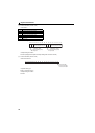
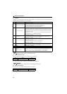
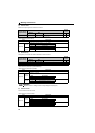
REMARKS
y The values of each bit, "0" and "1," indicate "OFF" and "ON."
Bit0 Bit1 Command
Forward rotation: 0 Reverse rotation: 0
Stop command
Forward rotation: 1 Reverse rotation: 0
Forward rotation
command
Forward rotation: 0 Reverse rotation: 1
Reverse rotation
command
Forward rotation: 1 Reverse rotation: 1
Stop command
Bit11
Signal Function/Operation
Operation mode Parameter write
0
Forcibly switched to Network
operation mode
Network operation is allowed
Switching to the PU operation
mode is disabled
Parameter write is disabled
(Note that the Pr.297 setting is
available when Pr.296 ≠ "9999.")
1
Operation mode (PU, NET)
switching is enabled
Output stop during Network
operation
Parameter write is enabled
(depending on Pr. 77 Parameter
write selection and each parameter
write conditions)