


I
1 OUTLINE 1
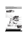
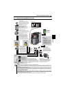
1.1 Product checking and parts identification......................................... 2
1.2 Inverter and peripheral devices ......................................................... 3
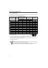
1.2.1 Peripheral devices .......................................................................................................................... 4
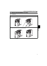
1.3 Removal and reinstallation of the cover ............................................ 5
1.3.1 Front cover...................................................................................................................................... 5
1.3.2 Wiring cover.................................................................................................................................... 7
1.4 Installation of the inverter and enclosure design.............................. 8
1.4.1 Inverter installation environment..................................................................................................... 8
1.4.2 Cooling system types for inverter enclosure................................................................................. 10
1.4.3 Inverter placement........................................................................................................................ 11
2 WIRING 13
2.1 Wiring ................................................................................................ 14
2.1.1 Terminal connection diagram ....................................................................................................... 14
2.2 Main circuit terminal specifications ................................................ 15
2.2.1 Specification of main circuit terminal ............................................................................................ 15
2.2.2 Terminal arrangement of the main circuit terminal, power supply and the motor wiring............... 15
2.2.3 Cables and wiring length .............................................................................................................. 17
2.3 Control circuit specifications ........................................................... 20
2.3.1 Control circuit terminal.................................................................................................................. 20
2.3.2 Wiring of control circuit ................................................................................................................. 21
2.3.3 Connecting the 24V external power supply .................................................................................. 23
2.3.4 Safety stop function ...................................................................................................................... 24
2.4 Connection of stand-alone option unit ............................................. 25
2.4.1 Connection of a dedicated external brake resistor (MRS type, MYS type, FR-ABR) ................... 25
2.4.2 Connection of the brake unit (FR-BU2) ........................................................................................ 27
2.4.3 Connection of the DC reactor (FR-HEL)....................................................................................... 28
3 PRECAUTIONS FOR USE OF THE INVERTER 29
3.1 EMC and leakage currents................................................................ 30
3.1.1 Leakage currents and countermeasures ...................................................................................... 30
3.1.2 EMC measures............................................................................................................................. 32
3.1.3 Power supply harmonics............................................................................................................... 34
3.1.4 Harmonic suppression guideline in Japan....................................................................................35
CONTENTS