


11
1
OUTLINE
Installation of the inverter and enclosure design
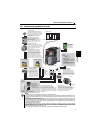
1.4.3 Inverter placement
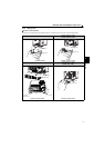
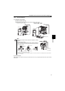
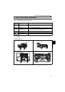
(1) Installation of the inverter
Enclosure surface mounting
Remove the front cover and wiring cover to fix the inverter to the surface.
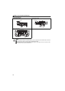
(2) Above inverter
Heat is blown up from inside the inverter by the small fan built in the unit. Any equipment placed above the inverter should be
heat resistant.
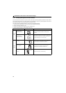
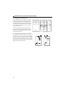
Note
When encasing multiple inverters, install them in parallel as a cooling
measure.
Install the inverter vertically.
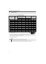
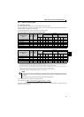
For heat dissipation and maintenance, take at least the clearances
shown in the table below from the inverter to the other devices and to
the enclosure surface.
∗1 Take 5cm or more clearances for 5.5K or higher.
∗2 When using the inverters at the surrounding air temperature of 40°C or less, the inverters can be installed without any clearance between
them (0cm clearance).
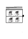
Front cover
Wiring cover
Front cover
Wiring cover
FR-E720-0.1KNF to 0.75KNF FR-E720-1.5KNF or higher
FR-E740-0.4KNF or higher
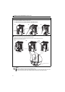
10cm or more
10cm or more
5cm
5cm
5cm
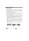
Measurement
position
-10 C to +50 C (non-freezing)
Measurement
position
1cm or
more
1cm or
more
1cm or
more
∗1, ∗2
∗1
∗1, ∗2
Vertical
Refer to the clearances
on the left.