


200
Causes and corrective actions
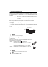
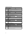
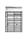
Operation panel
indication
E.OLT
Name
Stall prevention stop stop
Description
If the output frequency has fallen to 1Hz by stall prevention operation and remains for 3s, a fault (E.OLT) appears and
trips the inverter. OL appears while stall prevention is being activated.
E.OLT may not occur if stall prevention (OL) is activated during output phase loss.
Check point
Check the motor for use under overload. (Refer to page 102).
Corrective action
Reduce the load weight. (Check the Pr. 22 Stall prevention operation level setting.)
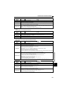
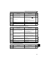
Operation panel
indication
E.BE
Name
Brake transistor alarm detection
Description
When a brake transistor alarm has occurred due to the large regenerative energy from the motor etc., the brake
transistor alarm is detected and the inverter trips.
In this case, the inverter must be powered OFF immediately.
Check point
Reduce the load inertia.
Check that the frequency of using the brake is proper.
Corrective action Replace the inverter.
Operation panel
indication
E.GF
Name
Output side earth (ground) fault overcurrent at start
Description
The inverter trips if an earth (ground) fault overcurrent flows at start due to an earth (ground) fault that occurred on
the inverter's output side (load side). Whether this protective function is used or not is set with Pr. 249 Earth (ground)
fault detection at start. When the setting of Pr. 249 Earth (ground) fault detection at start is the initial value (Pr. 249 ="0"),
this warning does not occur.
Check point
Check for a ground fault in the motor and connection cable.
Corrective action
Remedy the ground fault portion.
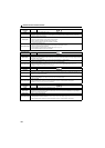
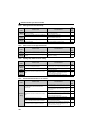
Operation panel
indication
E.LF
Name
Output phase loss
Description
If one of the three phases (U, V, W) on the inverter's output side (load side) is lost during inverter operation (except
during DC injection brake operation and when output frequency is under 1Hz), inverter stops the output. Whether the
protective function is used or not is set with Pr. 251 Output phase loss protection selection.
Check point
Check the wiring. (Check that the motor is normal.)
Check that the capacity of the motor used is not smaller than that of the inverter.
Corrective action
Wire the cables properly.
Check the Pr. 251 Output phase loss protection selection setting.
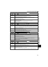
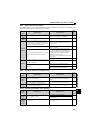
Operation panel
indication
E.OP1
Name
Communication option fault
Description
Inverter output is stopped when a fault occurs on the communication line of FL remote communication.
Check point
Check if the inverter's LED shows any fault.
Check if the FL-net dedicated cable has a break.
Check if the length of the FL-net dedicated cable is within the specified range.
Corrective action
Refer to "Troubleshooting in FL remote communication" on
page 209
, and take corrective actions for the fault.
Check the connection of the FL-net dedicated cable.
Check that each FL-net dedicated cable length between nodes is within the specified range.
(Refer to page 46).