


204
Check first when you have a trouble
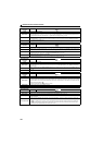
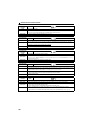
6.5 Check first when you have a trouble
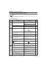
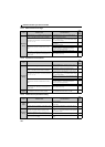
6.5.1 Motor does not start
POINT
If the cause is still unknown after every check, it is recommended to initialize the parameters (initial value) then
set the required parameter values and check again.
Check
points
Possible Cause Countermeasures
Refer
to
page
Main
Circuit
Appropriate power supply voltage is not applied.
(Operation panel display is not provided.)
Power ON a moulded case circuit breaker (MCCB), an
earth leakage circuit breaker (ELB), or a magnetic
contactor (MC). —
Check for the decreased input voltage, input phase loss,
and wiring.
Motor is not connected properly. Check the wiring between the inverter and the motor. 15
The jumper across P/+ and P1 is disconnected.
Securely fit a jumper across P/+ and P1.
When using a DC reactor (FR-HEL), remove the jumper
across P/+ and P1, and then connect the DC reactor.
28
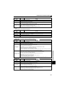
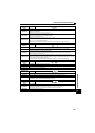
Input
Signal
Start signal is not input.
Check the start command source, and input a start
signal.
PU operation mode:
Network operation mode: STF/STR signal
57, 74
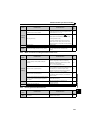
Both the forward and reverse rotation start signals (STF,
STR) are input simultaneously.
Turn ON only one of the forward and reverse rotation
start signals (STF or STR).
If STF and STR signals are turned ON simultaneously in
the initial setting, a stop command is given.
20
Frequency command is zero.
(RUN LED on the operation panel is flickering.)
Enter a frequency command. 58
Output stop signal (MRS) or error reset is ON.
(RUN LED on the operation panel flickers while MRS
signal or error reset is ON.)
Turn MRS signal or error reset OFF.
Inverter starts the operation with a given start command
and a frequency command after turning OFF MRS
signal or error reset.
Before turning OFF, ensure the safety.
57
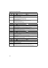
Shorting wires across S1 and PC and across S2 and
PC are disconnected even though the safety stop
function is not being used.
When not using the safety stop function, short across
terminals S1 and PC and across S2 and PC with
shorting wire.
24
was pressed.
(Operation panel indication is (PS).)
During the Network operation mode, check the method
of restarting from a input stop from the operation
panel.
195
The setting value "1" is set in the X12 signal (Bit11),
which gives a control input command through FL remote
communication.
Set "0" in the X12 signal (Bit11), which gives a control
input command through FL remote communication.
57
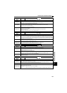
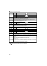
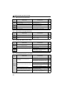
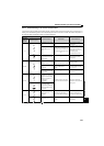
Parameter
Setting
Pr. 0 Torque boost setting is improper when V/F control is
used.
Increase Pr. 0 setting by 0.5% increments while
observing the rotation of a motor.
If that makes no difference, decrease the setting.
94
Pr. 78 Reverse rotation prevention selection is set.
Check the Pr. 78 setting.
Set Pr. 78 when you want to limit the motor rotation to
only one direction.
167
Pr. 13 Starting frequency setting is greater than the
running frequency.
Set running frequency higher than Pr. 13.
The inverter does not start if the frequency setting signal
is less than the value set in Pr. 13.
119
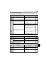
Frequency settings of various running frequency (such
as multi-speed operation) are zero.
Especially, Pr. 1 Maximum frequency is zero.
Set the frequency command according to the
application.
Set Pr. 1 higher than the actual frequency used.
105
Pr. 15 Jog frequency setting is lower than the Pr. 13
Starting frequency setting during the JOG operation.
Set Pr. 15 Jog frequency higher than Pr. 13 Starting
frequency.
171