


199
Causes and corrective actions
6
TROUBLESHOOTING
∗1 Resetting the inverter initializes the internal thermal integrated data of the electronic thermal relay function.
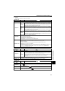
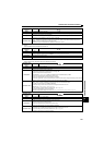
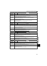
Operation panel
indication
E.THT
Name
Inverter overload trip (electronic thermal relay function)
Description
If the temperature of the output transistor element exceeds the protection level under the condition that a current not
less than the rated inverter current flows and overcurrent trip does not occur (230% or less), the electronic thermal
relay activates to stop the inverter output. (Overload capacity 150% 60s, 200% 3s)
Check point
Check that acceleration/deceleration time is not too short.
Check that torque boost setting is not too large (small).
Check that load pattern selection setting is appropriate for the load pattern of the using machine.
Check the motor for use under overload.
Check for too high surrounding air temperature.
Corrective action
Increase acceleration/deceleration time.
Adjust the torque boost setting.
Set the load pattern selection setting according to the load pattern of the using machine.
Reduce the load weight.
Set the surrounding air temperature to within the specifications.
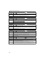
Operation panel
indication
E.THM
Name
Motor overload trip (electronic thermal relay function) ∗1
Description
The electronic thermal relay function in the inverter detects motor overheat due to overload or reduced cooling capability
during constant-speed operation and pre-alarm (TH display) is output when the integrated value reaches 85% of the
Pr. 9
Electronic thermal O/L relay
setting and the protection circuit is activated to stop the inverter output when the integrated
value reaches the specified value. When running a special motor such as a multi-pole motor or multiple motors, provide a
thermal relay on the inverter output side since such motor(s) cannot be protected by the electronic thermal relay function.
Check point
Check the motor for use under overload.
Check that the setting of Pr. 71 Applied motor for motor selection is correct. (Refer to page 125).
Check that stall prevention operation setting is correct.
Corrective action
Reduce the load weight.
For a constant-torque motor, set the constant-torque motor in Pr. 71 Applied motor.
Check that stall prevention operation setting is correct. (Refer to page 101).
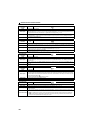
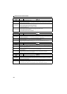
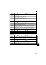
Operation panel
indication
E.FIN
Name
Heatsink overheat
Description
If the heatsink overheats, the temperature sensor is actuated and the inverter trips.
FIN signal is output through FL remote communication when the temperature rises to 85% of the heatsink overheat
protection temperature. (Refer to page 60)
Check point
Check for too high surrounding air temperature.
Check for heatsink clogging.
Check that the cooling fan is not stopped (Check that is not displayed on the operation panel).
Corrective action
Set the surrounding air temperature to within the specifications.
Clean the heatsink.
Replace the cooling fan.
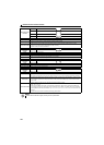
Operation panel
indication
E.ILF
Name
Input phase loss
Description
Inverter trips when function valid setting (=1) is selected in Pr. 872 Input phase loss protection selection and one phase of
the three phase power input is lost. (Refer to page 160).
It may function if phase-to-phase voltage of the three-phase power input becomes largely unbalanced.
Check point
Check for a break in the cable for the three-phase power supply input.
Check that phase-to-phase voltage of the three-phase power input is not largely unbalanced.
Corrective action
Wire the cables properly.
Repair a break portion in the cable.
Check the Pr. 872 Input phase loss protection selection setting.
Set Pr. 872 = "0" (without input phase loss protection) when three-phase input voltage is largely unbalanced.