


207
Check first when you have a trouble
6
TROUBLESHOOTING
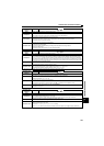
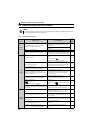
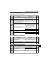
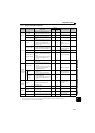
6.5.8 Speed varies during operation
When Advanced magnetic flux vector control or the slip compensation is selected, the output frequency varies between 0 and
2Hz as load fluctuates. This is a normal operation and not a fault.
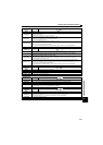
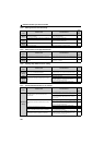
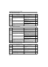
6.5.9 Operation mode is not changed properly
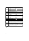
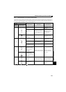
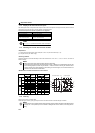
6.5.10 Operation panel display is not operating
Check
points
Possible Cause Countermeasures
Refer
to
page
Load Load varies during an operation.
Select Advanced magnetic flux vector control or
General-purpose magnetic flux vector control.
95
Input
signal
Frequency setting signal is varying. Check the frequency setting signal. —
Parameter
Setting
Pr. 80 Motor capacity and Pr. 81 Number of motor poles
setting is improper for the capacities of the inverter and
the motor for Advanced magnetic flux vector control or
General-purpose magnetic flux vector control.
Check the Pr. 80 Motor capacity and Pr. 81 Number of
motor poles setting.
95
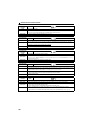
Fluctuation of power supply voltage is too large.
Change the Pr. 19 Base frequency voltage setting (about
3%) under V/F control.
107
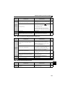
Hunting occurs by the generated vibration, for example,
when structural rigidity at load side is insufficient.
Disable automatic control functions, such as energy
saving operation, fast-response current limit function,
regeneration avoidance function, Advanced magnetic
flux vector control, General-purpose magnetic flux
vector control, and stall prevention.
Adjust so that the control gain decreases and the level of
safety increases.
—
Change Pr. 72 PWM frequency selection setting.
163
Others
Wiring length exceeds 30m when Advanced magnetic
flux vector control or General-purpose magnetic flux
vector control is performed.
Perform offline auto tuning. 127
Wiring length is too long for V/F control, and a voltage
drop occurs.
Adjust Pr. 0 Torque boost by increasing with 0.5%
increments for low-speed operation.
94
Change to Advanced magnetic flux vector control or
General-purpose magnetic flux vector control.
95
Check
points
Possible Cause Countermeasures
Refer
to
page
Input
signal
Start signal (STF or STR) is ON.
Check that the STF and STR signals are OFF.
When either is ON, the operation mode cannot be
changed.
57, 74
"0" is set in the X12 signal (Bit11), which gives a control
input command through FL remote communication.
Set "1" in the X12 signal (Bit11), which gives a control
input command through FL remote communication.
57
Others
FL-net dedicated cable is not installed properly. (The
cable has contact faults and breaks.)
Install the FL-net dedicated cable properly.
48
Check
points
Possible Cause Countermeasures
Refer
to
page
Main
Circuit
Wiring or installation is improper.
Check for the wiring and the installation.
14Make sure that the connector is fitted securely across
terminal P/+ and P1.
Main
Circuit
Control
Circuit
Power is not input. Input the power. 14