


15
2
WIRING
Main circuit terminal specifications
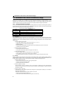
2.2 Main circuit terminal specifications
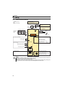
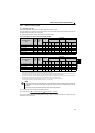
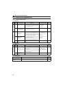
2.2.1 Specification of main circuit terminal
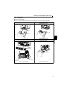
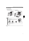
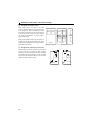
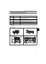
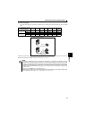
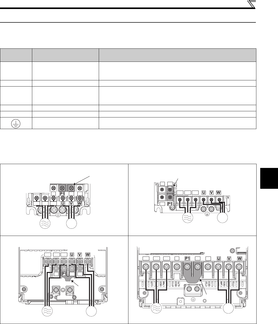
2.2.2 Terminal arrangement of the main circuit terminal, power supply and the motor
wiring
Three-phase 200V class
Terminal
Symbol
Terminal Name Description
R/L1,
S/L2,
T/L3
AC power input Connect to the commercial power supply.
U, V, W Inverter output Connect a three-phase squirrel-cage motor.
P/+, PR Brake resistor connection
Connect a brake resistor (FR-ABR, MRS type, MYS type) across terminals P/+ and
PR.
(The brake resistor cannot be connected to the 0.1K or 0.2K.)
P/+, N/- Brake unit connection Connect the brake unit (FR-BU2).
P/+, P1 DC reactor connection Remove the jumper across terminals P/+ and P1 and connect a DC reactor.
Earth (Ground) For earthing (grounding) the inverter chassis. Must be earthed (grounded).
FR-E720-0.1KNF to 0.75KNF FR-E720-1.5KNF to 3.7KNF
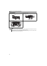
FR-E720-5.5KNF, 7.5KNF FR-E720-11KNF, 15KNF
MotorPower supply
N/-
P/+ PR
IM
R/L1 S/L2 T/L3
Jumpe
r
Motor
Power supply
N/-
P/+
PR
IM
R/L1 S/L2 T/L3
Jumper
Motor
Power supply
IM
N/-
P/+
PR
R/L1 S/L2 T/L3
Jumper
N/-
P/+
PR
R/L1 S/L2 T/L3
Jumper
MotorPower supply
IM