


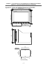
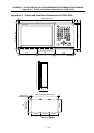
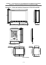
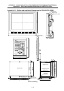

APPENDIX 7 CABLE MANUFACTURING DRAWINGS
I - 85
APPENDIX 7 CABLE MANUFACTURING DRAWINGS
As a rule, most F/R cables used with this product are not sold by Mitsubishi. Thus,
manufacture the required cables using the cable manufacturing drawings on the following pages as a
reference. Note that the cable-compatible connectors can be purchased from Mitsubishi.
If crimp tools are not available when manufacturing the power supply cable (R200, R220) and
communication cable (R211), the cables can be manufactured by soldering a wire and connector as
shown in the following procedures.
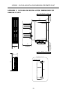
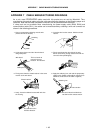
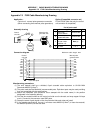
1. Carry out preparatory soldering onto the wire.
(Peel 3.5mm of the sheath.)
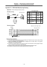
2. Insert the wire into the contact. Hold the sheath
retainer.
Soldering
iron
Solder
Wire
Contact
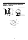
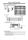
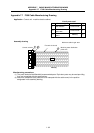
3. Lightly press down one side of the wire barrel
using radio pliers.
4. Firmly press down the other side of the wire
barrel. (Press firmly enough that the wire will not
come out when pulled lightly.)
W
ire barrel
This is a barrier to
prevent incorrect
insertion. Do not bend.
Radio pliers
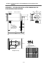
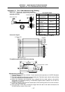
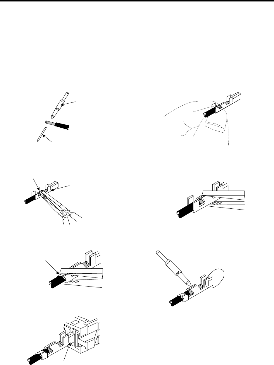
5. Firmly press down the sheath retainer in the same
manner as the wire barrel.
6. Apply the soldering iron, and melt the preparatory
solder inside. (Better results will be achieved if an
additional, small amount of solder is applied.)
Sheath retainer
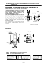
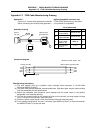
7. Lastly, insert the soldered contact with wire into
the housing.
Contact section
Soldering iron
Be careful that the solder does
not flow into the contact section.
Pay attention to the
insertion direction.