


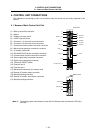
4. CONTROL UNIT CONNECTIONS
4.3 Connecting the Communication Terminal
I - 22
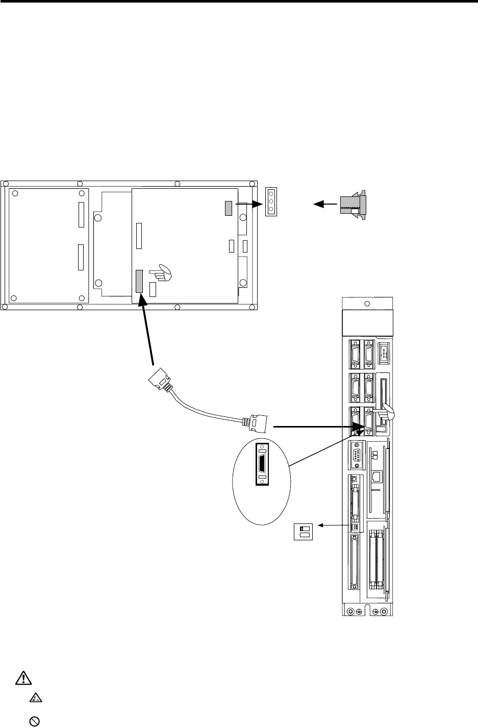
4.3 Connecting the Communication Terminal
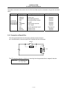
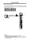
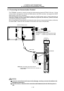
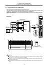
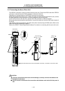
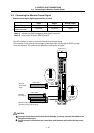
The TERMINAL connector is used to connect the communication terminal (FCUA-LD100, etc.). On the
communication terminal side, connect the R000 cable to the CR02 connector, and supply the 24VDC
power supply to the CR01 connector.
Use the enclosed connector and contact to supply the +24VDC power supply. If the accessories are
insufficient, prepare the one-ended CN220 connector set (optional, with one end). (Refer to the cable
manufacturing drawings for details.)
When connecting the communication terminal and control unit one-on-one as shown below, confirm that
the switch SW2-1 under the DIO connector of the control unit is set to ON (left side).
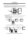
FCUA-LD100 rear view
Recommended adaptive connector
(Enclosed with FCUA-LD100)
Connector : 2-178288-3 (Tyco Electronics AMP)
Contact : 1-175218-5 (Tyco Electronics AMP)
Control unit
R000 cable
Note)
When connecting the control unit and
communication terminal one-on-one, set SW2-1 to
ON (left side).
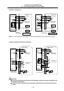
MITSUBISHI
CR01
12
TERMINAL
Y
ON
SW2
TERMINAL
connector
pin No.
MELDAS
C64
SERVO1
SERVO2
DC24VIN
ENC
HANDLE
ICCARD
SIO
TERMINAL
SKIP
FG
0V
24VDC
CR02
1
10
11
20
CAUTION
Incorrect connections could cause device damage, so always connect the cables to the
designated connectors.
Do not connect or disconnect the connection cable between each unit while the power is
ON.