


6. CONNECTION OF REMOTE I/O UNIT
6.14 Connection of FCUA-DX14 Unit and Analog Input/Output Signal
I
- 72
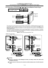
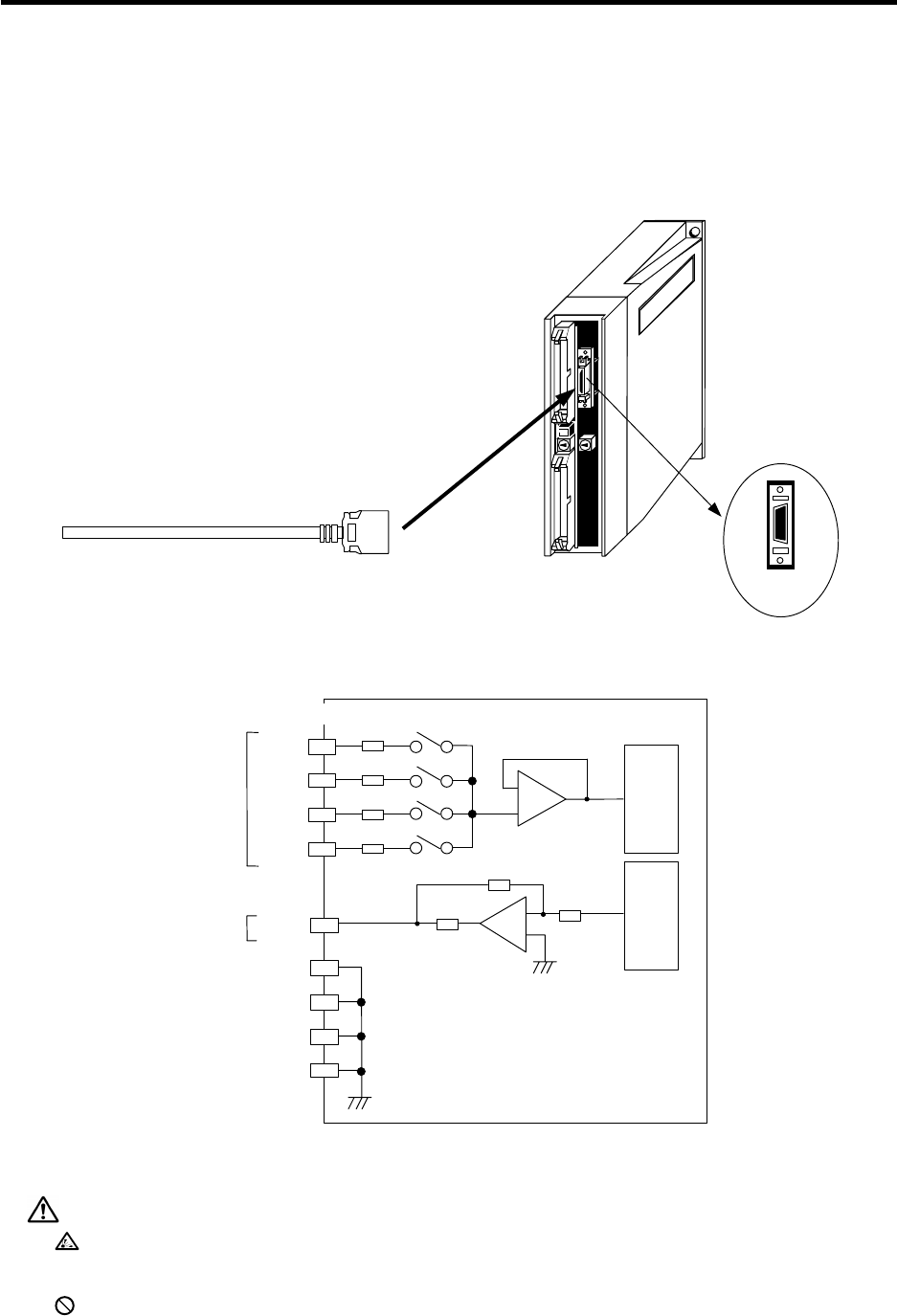
6.14 Connection of FCUA-DX14 Unit and Analog Input/Output Signal
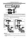
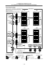
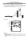
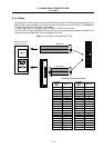
For the analog input/output signal, the R031 cable is connected to AI0. Up to four input points and one
output point of the analog input/output signal can be connected. When manufacturing the R031 cable,
use the CS000 connector set (optional, with both ends).
A
IO
FCUA-DX14
1
10
11
20
Pin No.
R031 cable
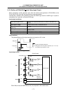
Input/output circuit
DAC
220
Ω
R
R
150
Ω
A
DC
A
10
A
0
FCUA-DX14
7
GND
Input
Output
Connector pin No.
GND
GND
GND
A
11
A
12
A
13
13
12
2
3
150
Ω
150
Ω
150
Ω
1
11
5
15
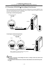
CAUTION
Incorrect connections could damage the device, so always connect the cable to the
designated connector.
Do not connect or disconnect the connection cables between each unit while the power
is ON.