


APPENDIX 7 CABLE MANUFACTURING DRAWINGS
Appendix 7.3 F320 Cable Manufacturing Drawing
I - 88
Appendix 7.3 F320 Cable Manufacturing Drawing
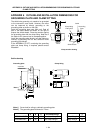
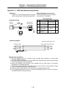
Application :
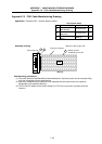
Control unit - manual pulse generator connection
(When connecting one manual pulse generator)
Option (Compatible connector set)
FCUA-CS000 (Note that only the control
unit connector is compatible)
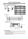
List of parts used
F320
F320
Note (3)
1 2
3
4
Control
unit side
Manual pulse
generator side
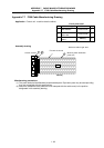
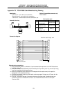
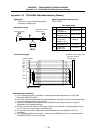
Assembly drawing
No. Part name/type Maker Q'ty
1
Connector
10120-3000VE
Sumitomo 3M 1
2
Connector case
10320-52F0-008
Sumitomo 3M 1
3
Wire material
UL1061-2464
AWG22
× 6P
Note (1)
(1)
4
Crimp terminal
V1.25-3
J. S. T 4
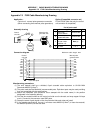
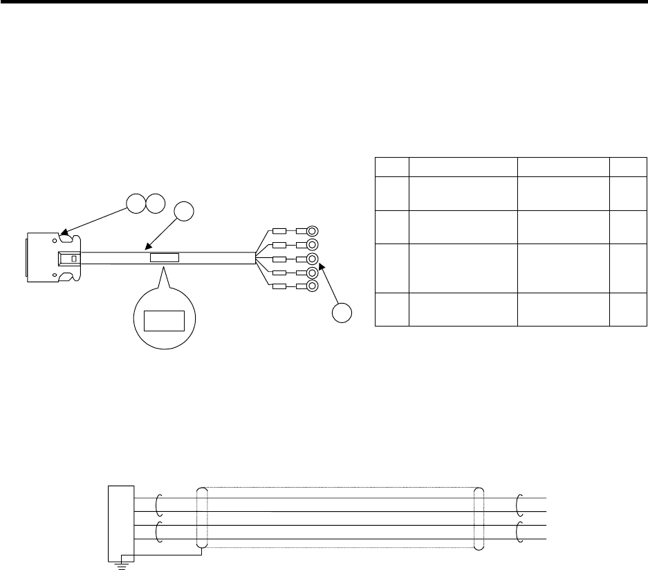
Case GND plate
Manual pulse generator side
Maximum cable length: 30m
Control unit side
4
14
6
1
1HA
1HB
+12V
GND
1H
A
1HB
+12V
GND
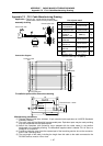
Connection diagram
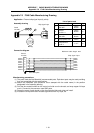
Manufacturing precautions
(1) The wire material shall be a shielded, 6-pair stranded cable equivalent to UL1061-2464
Standards AWG22 (0.3mm
2
).
(2) The parts used shall be Mitsubishi recommended parts. Equivalent parts may be used providing
they are compatible with the specifications.
(3) Attach the nameplate (with protective cover stamped with the cable name) in the position
designated in the assembly drawing.
(4) Fold the wire material shield on the control unit side over the sheath, and wrap copper foil tape
over it. Connect to the connector case GND plate.
(5) Stamp the name of each signal on the crimp terminal side mark tube and install.
(6) In the catalog specifications, the part 1 connector uses AWG24 (0.2mm
2
) or less wire material,
but AWG22 (0.3mm
2
) can also be used.