


4. CONTROL UNIT CONNECTIONS
4.11 Connecting Other Peripheral Devices
I - 37
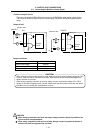
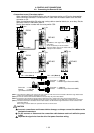
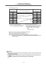
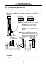
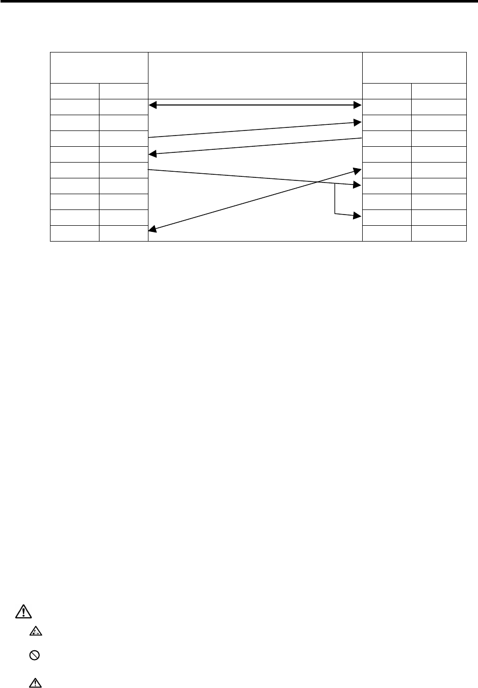
(5) RS-232C cable (F316)
MELDAS C6/C64 side
(20pin half-pitch)
GOT side
(9pin D-SUB)
Signal Pin No.
Cable connection & Signal direction
Pin No. Signal
GND 1 1 CD
2 RD(RXD)
SD 6 3 SD(TXD)
RD 16 4 DTR(ER)
ER(DTR) 18 5 SG(GND)
6 DSR(DR)
7 RS(RTS)
8 CS(CTS)
GND 11
9
-
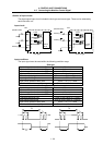
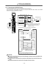
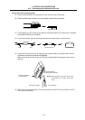
[GOT side connector (Recommended)]
The recommended connector on the GOT side is
as indicated below. The connector on the partner
side has to be matched with this connector.
9pin D-sub (Male) Inch screw fixing type
(DDK)
17LE-23090-27(D3CC)
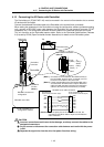
[NC side connector (Recommended)]
Connector:10120-3000VE (Sumitomo 3M)
Case:10320-52F0-008 (Sumitomo 3M)
(Note 1) The conversion cable is not available from Mitsubishi.
(Note 2) Do not connect anything to the open pins.
(Note 3) Keep the total length of the cable to 15m or less.
(Note 4) For details on GOT, refer to “GOT-A900 Series User’s Manual (GT Works2
Version1/GT Designer2 Version1 compatible Connection System Manual)” and other
relevant materials.
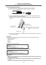
CAUTION
Incorrect connections could cause device damage, so always connect the cables to the
designated connectors.
Do not connect or disconnect the connection cable between each unit while the power
is ON.
Separate the signal wire from the drive line/power line when wiring.