


4. CONTROL UNIT CONNECTIONS
4.10 Connecting the RS-232C Device
I - 34
4.10 Connecting the RS-232C Device
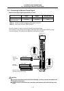
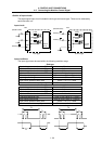
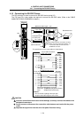
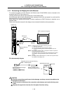
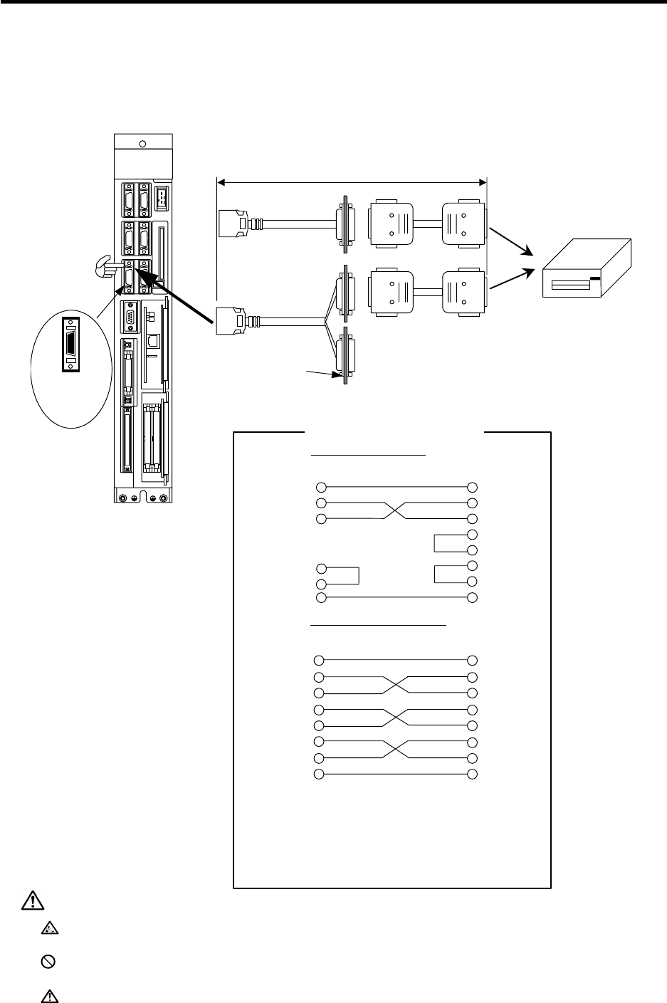
The SIO connector is used to connect the RS-232C device (serial I/O).
The F310 and F311 relay cables are required to connect the RS-232C cable. (Refer to the CABLE
MANUFACTURING DRAWINGS for details.)
SIO
LED1
Control unit
1
10
11
20
SIO
connector
pin No.
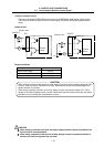
F311 cable
F310 cable
RS-232C relay
o
r
RS-232C/RS-422
(For GPP)relay
RS-232C device
MELSEC perfipheral device connection connecto
r
(Note)
When connecting GPP with RS-232C, use
a conversion cable, and connect to the
TERMINAL connector.
Cabinet side
w
all
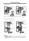
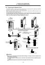
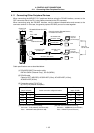
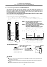
The specifications of the cross cable are shown below.
Cross cable connection
For DC code control
Panel relay
connector side
RS-232C
device side
1 GND
2 TXD
3 RXD
1 GND
2 TXD
3 RXD
4 RTS
5 CTS
6 DSR
20 DTR
7 GND
1 GND
2 TXD
3 RXD
4 RTS
5 CTS
6 DSR
20 DTR
7 GND
1 GND
2 TXD
3 RXD
4 RTS
5 CTS
6 DSR
20 DTR
7 GND
6 DSR
20 DTR
7 GND
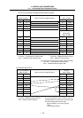
For RS/CS code control
RS-232C
device side
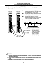
Recommended adaptive connector
Connector : HDBB-25PF(05)(Hirose Electric)
Case : HDB-CTF(Hirose Electric)
<Caution>
• Do not connect anything to the open pins.
• Keep the total cable length at 15m or less.
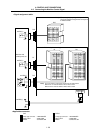
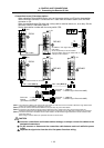
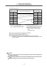
Cross cable
Cross cable
Maximum cable length:15m
RS232C RS422
Panel relay
connector side
CAUTION
Incorrect connections could cause device damage, so always connect the cables to the
designated connectors.
Do not connect or disconnect the connection cable between each unit while the power
is ON.
Separate the signal wire from the drive line/power line when wiring.