


4. CONTROL UNIT CONNECTIONS
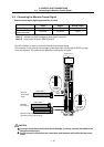
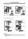
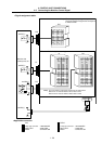
4.8 Connecting the Machine Control Signal
I - 31
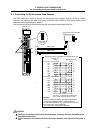
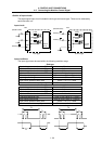
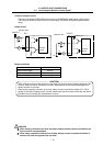
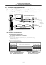
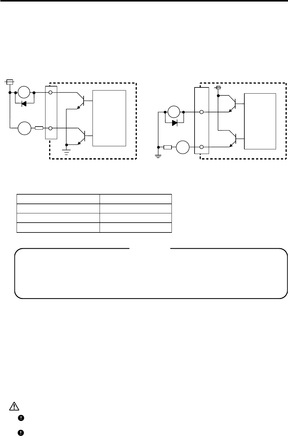
<Outline of output circuit>
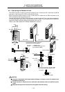
There are a sink type (HR881/882) and source type (HR883/884) digital signal output circuits.
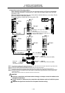
The SA (servo READY) output circuit is a source type. Use within the following specifications
range.
Output circuit
R
Source t
y
pe
(
HR883/884/SA
)
RA
PL
0V
24VDC(+)
DIO/DO
R
(Machine side)
Control
circuit
24VDC(+)
Sink type (HR881/882)
RA
PL
DO
(Machine side)
Control
circuit
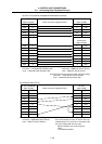
Output conditions
Insulation method Non-insulated
Rated load voltage 24VDC
Maximum output current 60mA
Output delay time
40
µs
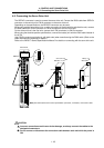
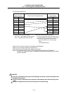
When using an inductive load such as a relay, always connect a diode (voltage resistance 100V
or more, 100mA or more) in parallel to the load. Note that the device could be damaged if the
diode's direction is incorrect.
When using a capacity load such as a lamp, always connect a protective resistor (R = 150Ω)
serially to the load to suppress rush currents. (Make sure that the current is less than the above
tolerable current including the instantaneous current.)
<CAUTION>
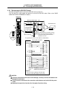
CAUTION
When using an inductive load such as relays, always connect a diode in parallel to the
load as a noise countermeasure.
When using a capacitive load such as a lamp, always connect a protective resistor in
series to the load to suppress rush currents.