


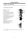
4. CONTROL UNIT CONNECTIONS
4.6 Connecting the Servo Drive Unit
I - 25
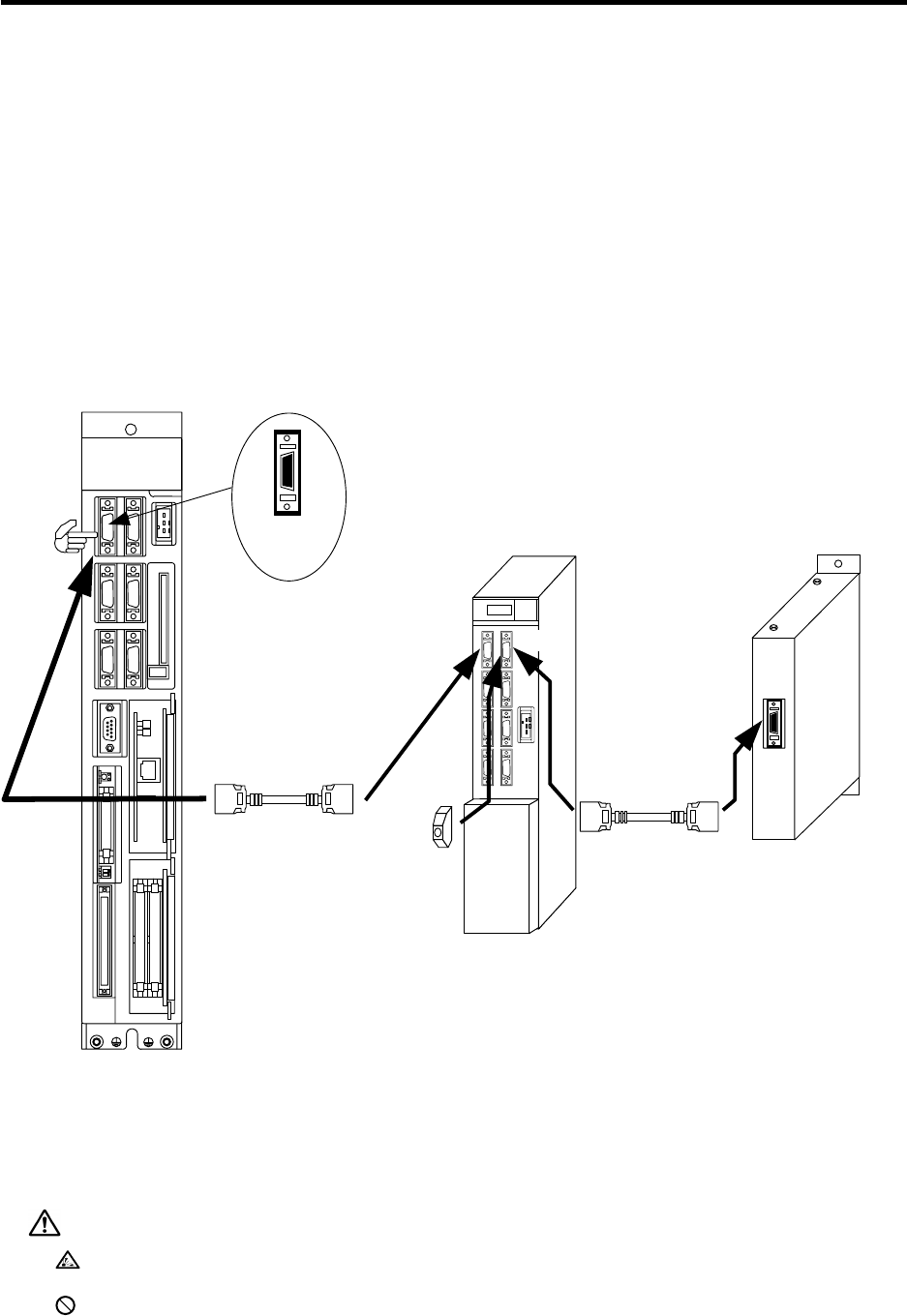
4.6 Connecting the Servo Drive Unit
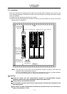
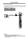
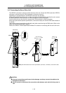
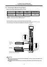
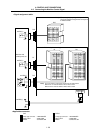
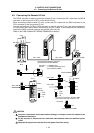
The SERVO1 connector is used to connect the servo drive unit. Connect the R000 cable from SERVO1
connector on the control unit to CN1A connector on the servo drive unit.
Depending on the specifications, the SERVO2 connector may be used.
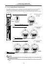
When using multiple servo drive units, or when connecting in parallel with the spindle drive unit, connect
the R000 cable from CN1B connector to CN1A connector on the next drive unit.
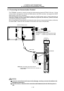
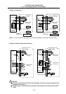
On the drive unit that is the final axis, connect the A-TM (terminator) to CN1B connector.
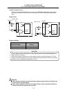
When using the absolute position specifications, connect the battery unit with the R000 cable instead of
the A-TM.
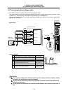
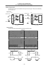
Use CS000 connector set (optional, with both ends) when manufacturing the R000 cable. (Refer to the
cable manufacturing drawings for details.)
Refer to the "MDS-C1 Series Specifications Manual" for details on connecting with the servo drive unit.
or
Servo drive unit
MDS-B/C1-V1/V2-
A
-TM
Note)
The R000 cable has the same specifications (connector, connection) as the SH21 cable.
SERVO
SKIP
DIO
EXT2
SERVO1
EXT1
MAINTENANCE
LED1 LED2
ENC HANDLE
SIO TERMINAL
IC CARD
DC24V IN
SERVO2
MITSUBISHI
MELDAS
C64
R000 cable
R000 cable
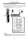
Control unit
CN1A
1
10
11
20
SERVO1
connector
pin No.
CN1A1
Battery unit
MDS-A-BT-
CN1B
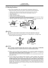
CAUTION
Incorrect connections could cause device damage, so always connect the cables to the
designated connectors.
Do not connect or disconnect the connection cable between each unit while the power is
ON.