


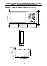

APPENDIX 7 CABLE MANUFACTURING DRAWINGS
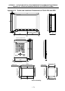
Appendix 7.1 F310 Cable Manufacturing Drawing
I - 86
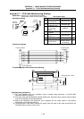
Appendix 7.1 F310 Cable Manufacturing Drawing
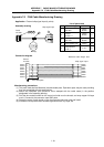
Application : Control unit - serial device connection
(Cable from control unit to junction plate.) List of parts used
1
2
3
4
5
6
7
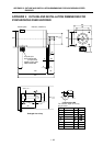
F310
F310
Note (3)
Control
unit side
Junction
plate side
A
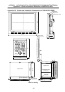
ssembly drawing
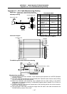
No. Part name/type Maker Q’ty
1
Connector
10120-3000VE
Sumitomo 3M
1
2
Connector case
10320-52F0-008
Sumitomo 3M
1
3
Wire material
UL1061-2464
AWG22
× 6P
Note (1)
(1)
4
Connector
CDB-25S
Hirose Electric
1
5
Contact
CD-SC-111
Hirose Electric
7
6
Lock nut HD-LNA Hirose Electric
2
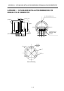
7
F installation plate
N750D714H01
Mitsubishi Electric
(Refer to dimen-
sion drawing)
1
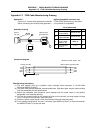
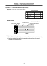
Case GND plate
Junction plate
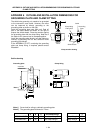
RS-232C
Maximum cable length: 8m Note (4)
Control unit side
SIO
2
12
3
13
4
14
1
3
2
5
4
6
20
7
RXD
TXD
CTS
RTS
DSR
DTR
SG
Connection diagram
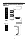
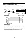
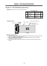
(5.5)
5.5
65
47.1
±
0.2
42.6
±
0.2
2-R2.5
2-R1.75
5
38
76
6
±0.1
12
24
Plate thickness: 1.6mm
F installation plate outline dimensions drawing
Manufacturing precautions
(1) The wire material shall be a shielded, 6-pair stranded cable equivalent to UL1061-2464
Standards AWG22 (0.3mm
2
).
(2) The parts used shall be Mitsubishi recommended parts. Equivalent parts may be used providing
they are compatible with the specifications.
(3) Attach the nameplate (with protective cover stamped with the cable name) in the position
designated in the assembly drawing.
(4) The total length of the cable, including the length from this cable to the cable connected to the
RS-232C device, must be 15m or less.