


5. CONNECTION OF COMMUNICATION TERMINAL
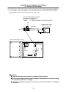
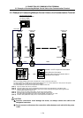
5.5 Example of Connecting Multiple Control Units to the Communication Terminal
I
- 54
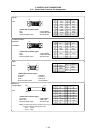
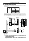
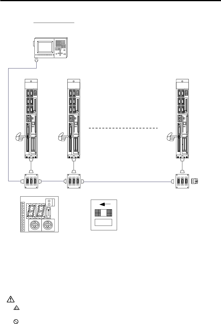
5.5 Example of Connecting Multiple Control Units to the Communication Terminal
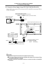
R000 cable
Communication terminal
DUT32+KB20/DUN33+KB20
/LD100/LD10+KB20
/CT100/CR10+KB10
LED1
Control unit
C6/C64
SW2-1
(ON)
TERMINAL
R000
LED1
Control unit
C6/C64
SW2-1
(OFF)
TERMINAL
R000
LE
D1
Control unit
C6/C64
SW2-1
(OFF)
TERMINAL
R000
CR02
HR591
R000
R000
HR591 HR591
Terminator
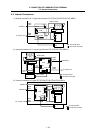
M-TM
ON
1
2
SW2
SW1
CS1 CS2
0 0
CS1
CS2
SW1
ON
OFF
2 1
LDCON
LED1 LED2
BAT
Set SW2-1 to OFF except for the final station.
Set to ON for the final station.
The final station refers to the station with no
subsequent slave stations.
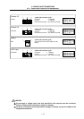
When connecting multiple control units, the station No. of each control unit must be set.
To set the station No., set SW1 to ON, set the rotary switch CS1 to "D", set the station No. in CS2, and turn the power
ON. After setting, return each switch to their original settings.
The same station No. cannot be set in duplicate for multiple control units.
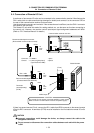
(Note 1) Up to 16 control units can be connected.
(Note 2) The R000 cable has the same specifications (both connector and specifications) as the SH21 cable.
(Note 3) Install the terminator M-TM to the HR591 card for the control unit having the longest cable length from the
communication terminal (LD100, etc.).
(Note 4) Set the control unit's slide switch SW2-1 to ON only for the final station.
(Note 5) The total length of the cable connected to each unit must be 30m or less.
The cable connected between the control unit and HR591 card must be 1m or less.
(Note 6) An R001 cable (distribution cable) can be used instead of the HR591 card.
CAUTION
Incorrect connections could damage the device, so always connect the cable to the
designated connector.
Do not connect or disconnect the connection cables between each unit while the power
is ON.