


4. CONTROL UNIT CONNECTIONS
4.8 Connecting the Machine Control Signal
I - 27
4.8 Connecting the Machine Control Signal
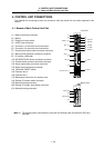
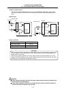
Machine input/output signal types and No. of points
Input Output Analog output
Standard control unit
16 points (Note 1) 1 point (Note 2)
–
Extension DIO card
(option mounted)
32 points 32 points 1 point
(Note 1) Includes one EMG (emergency stop signal) input point.
(Note 2) Uses as the SA (servo READY) output.
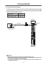
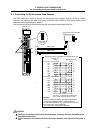
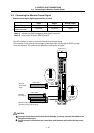
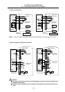
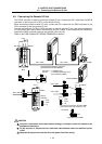
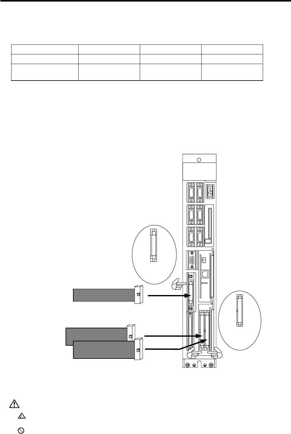
The DIO connector is used to connect the machine input/output signal.
This connector is also used for the emergency stop signal input and SA (servo READY) output.
Up to two extension DIO cards can be added by mounting with the option.
DO
Machine
input/output
signal
DIO
F350 cable
DI
Control unit
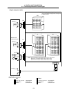
SKIP
DIO
EXT2
SERVO1
EXT1
MAINTENANCE
LED1 LED2
ENC HANDLE
SIO TERMINAL
IC CARD
DC24V IN
SERVO2
MITSUBISHI
MELDAS
C64
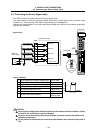
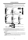
DIO
connector
pin No.
A
1
A
10
B1
B10
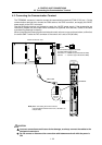
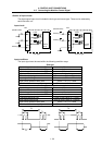
F351 cable
Machine
input signal
Machine output signal
(including analog output signal)
DI/DO
connector
pin No.
B20
B1
A
20
A
1
CAUTION
Incorrect connections could cause device damage, so always connect the cables to the
designated connectors.
Do not connect or disconnect the connection cable between each unit while the power
is ON.