


4. CONTROL UNIT CONNECTIONS
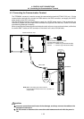
4.8 Connecting the Machine Control Signal
I - 30
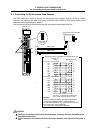
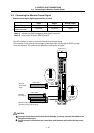
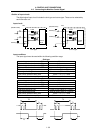
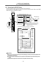
<Outline of input circuit>
The digital signal input circuit includes the sink type and source type. These can be selected by
each connector unit.
Input circuit
Control
circuit
2.2kΩ
COM
2
4VDC(+)
DIO
0V
(Machine side)
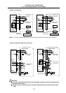
Sink type
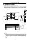
0V
2.2k
Ω
2.2k
Ω
2.2k
Ω
(Machine side)
0V
COM
DIO
24VDC(+)
24VDC(+)
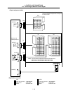
Source type
Control
circuit
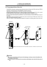
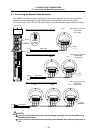
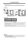
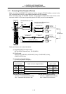
Input conditions
The input signal must be used within the following condition range.
Sink type
Input voltage at external contact ON 6V or less
Input current at external contact ON 9mA or more
Input voltage at external contact OFF 20V or more
Input current at external contact OFF 2mA or less
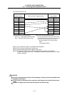
Tolerable chattering time 2.2ms or less (Refer to T1 below)
Input signal holding time 40ms or more (Refer to T2 below)
Input circuit operation delay time
2.2ms
≤ T3≒T4 ≤ 16ms
Machine side contact capacity 30V or more, 16mA or more
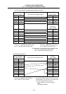
Source type
Input voltage at external contact ON 18V or more
Input current at external contact ON 9mA or more
Input voltage at external contact OFF 4V or less
Input current at external contact OFF 2mA or less
Tolerable chattering time 2.2ms or less (Refer to T1 below)
Input signal holding time 40ms or more (Refer to T2 below)
Input circuit operation delay time
2.2ms
≤ T3≒T4 ≤ 16ms
Machine side contact capacity 30V or more, 16mA or more
T1 T1 T1T1
T2T2
T4 T4 T3T3