


6. CONNECTION OF REMOTE I/O UNIT
6.2 Names of Each Remote I/O Unit Section
I - 56
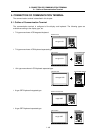
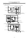
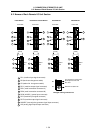
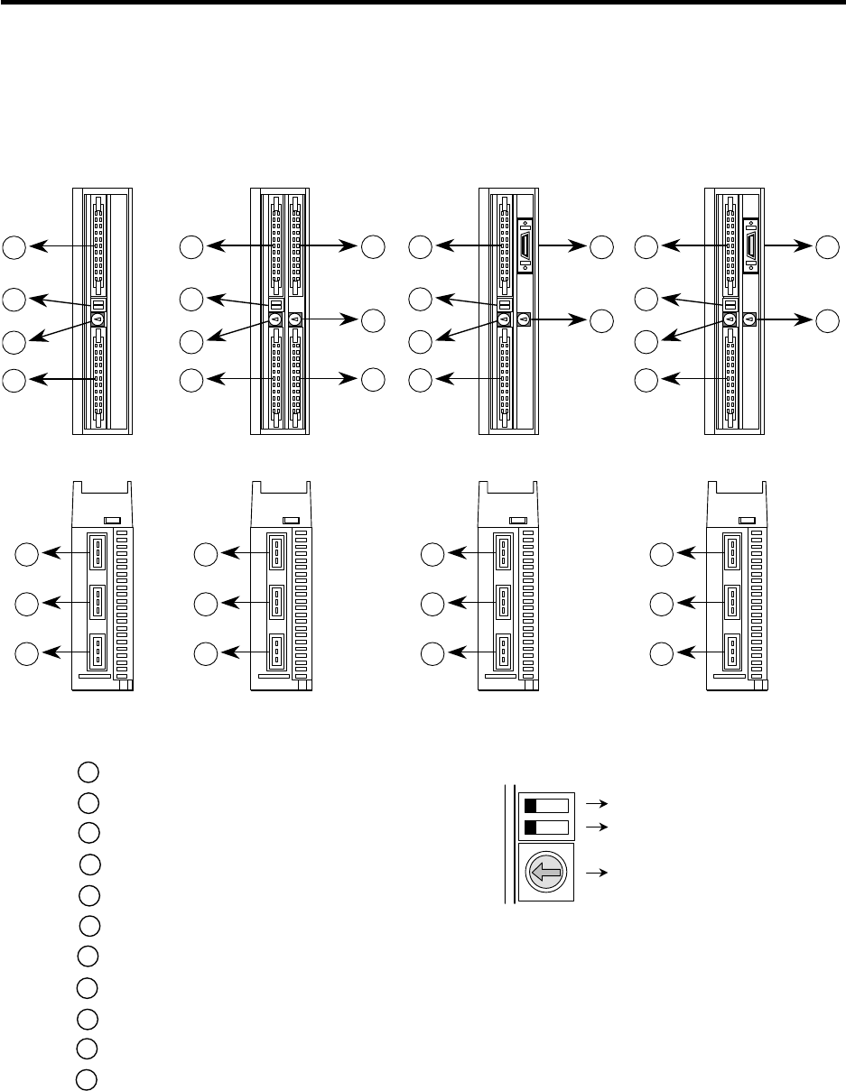
6.2 Names of Each Remote I/O Unit Section
DS
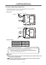
FCU
A
-DX10
Front view
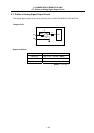
FCU
A
-DX11
/
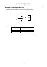
FCU
A
-DX12
FCU
A
-DX13
FCU
A
-DX14
5
6
7
(Front)
Bottom
view
5
6
7
5
6
7
5
6
7
11
3
1
2
3
4
1
2
3
4
8
3
9
1
2
3
4
10
3
1
2
3
4
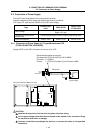
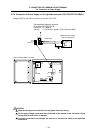
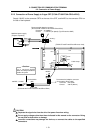
1 DI-L (machine input signal connector)
2 DS (baud rate changeover switch)
3 CS (station No. changeover switch)
4 DO-L (machine output signal connector)
5 RIO1 (serial connection connector #1)
6 RIO2 (serial connection connector #2)
7 DCIN (24VDC(+) power input connector)
8 DI-R (machine input signal connector)
9 DO-R (machine output signal connector)
10 HANDLE (manual pulse generator signal input connector)
11 AIO (analog signal input/output connector)
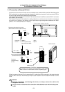
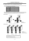
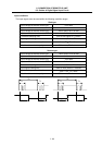
CS
For changeover of baud rate.
Normally set to left side.
Not used
Selection of station No.
Enlarged drawing of DS and CS
1
4
2
5
6
7
A
D
9
B
F
E
0
C
8
3
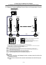
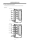
Front view Front view Front view
(Front) (Front) (Front)
Bottom
view
Bottom
view
Bottom
view
(Back) (Back) (Back) (Back)