


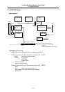
2. EXPLANATION OF MODULE FUNCTIONS
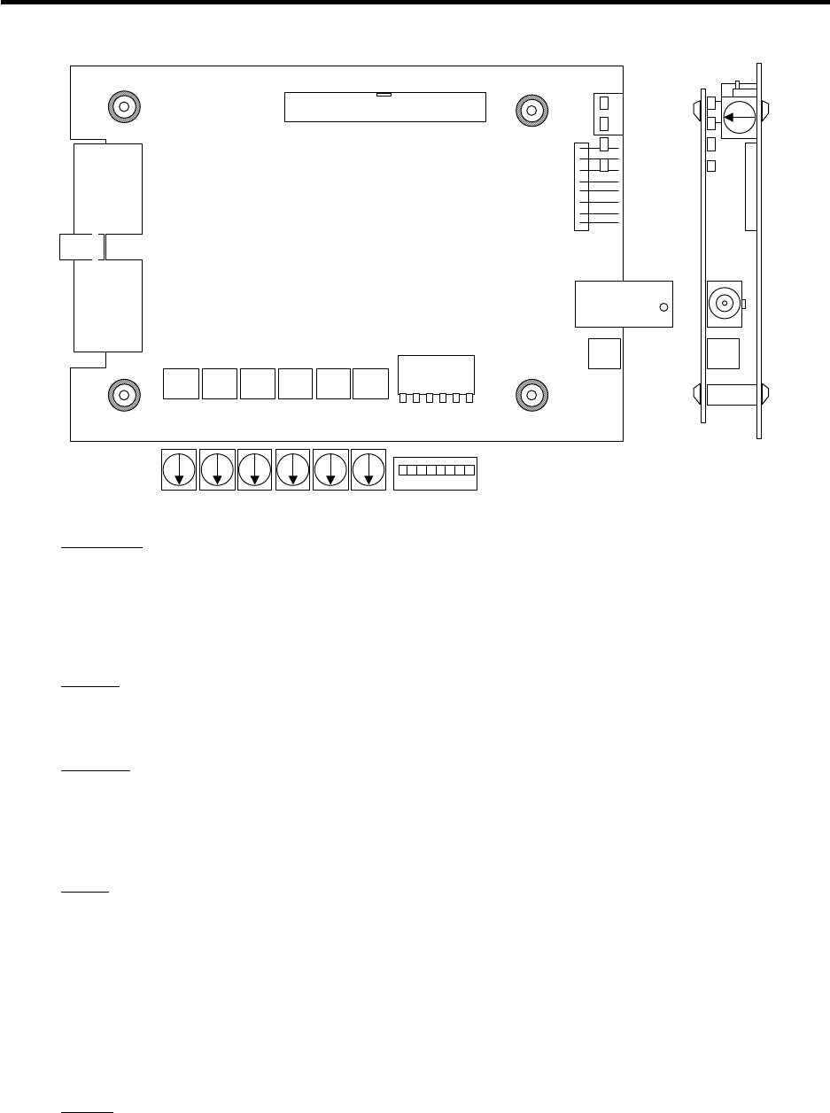
2.6 HR877/878 Card
II - 10
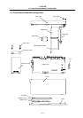
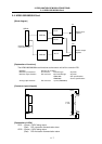
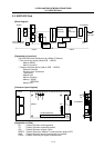
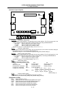
[Connector layout diagram]
NETWORK
x 100 x 10 x 10 x 1x 1
GROUP STATION DIPSW
MODE
ISP
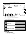
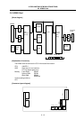
[Explanation of settings]
NETWORK : Network No. setting switch
Set the network number between 1 and 239 with the three rotary switches. The I/F board group No. is the
number used when setting the local station network number if connecting to MELSECNET/10.
×100 switch : Set the 100th place of the network number.
×10 switch : Set the 10th place of the network number.
×1 switch : Set the 1st place of the network number.
Set within the range of 1 to 239. (Default setting ×100: 0 ×10: 0 ×1: 1)
GROUP
: Group No. setting switch
Set the group number with the rotary switch. The I/F board group No. is the number used when setting the
local stations' group No. if connecting to MELSECNET/10.
Set within the range of 1 to 9. 0 means that no group is designated. (Default setting: 0)
STATION
: Station number setting switch
Set the station numbers between 01 and 64 with the two rotary switches. The I/F board group No. is the
number used when setting the local station number (normal station) if connecting to MELSECNET/10.
×10 switch : Set the 10th place of the station number.
×1 switch : Set the 1st place of the station number.
Set within the range of 1 to 64. (Default setting ×10: 0 ×1: 1)
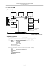
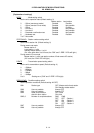
MODE
: Mode setting switch
0: Online (automatic parallel-off valid)
1: Online (automatic parallel-off invalid) OFF ON
2: Offline SW1 : PC-PC network Remote I/O network
3 to 9: Test mode SW2 : Normal station Control station
D: Network No. confirmation SW3 : Common parameter Default parameter
E: Group No. confirmation SW4, 5 : Number of stations
F: Station No. confirmation off, off on, off off, on on, on
8 stations 16 stations 32 stations 64 stations
SW6, 7 : Size off, off on, off off, on on, on
2K point 4K point 6K point 8K point
(Default setting: 0)
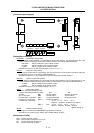
DIPSW
: Network condition setting
This switch is used to set the MELSECNET/10 operation conditions.
This switch is not used currently. (Always OFF) (Default setting: All OFF)
[Explanation of LEDs]
RUN : (Green) ON when normal
ERR. : (Red) ON when hardware error occurs
SD : (Green) ON during transmission
RD : (Green) ON during reception