


I
CONTENTS
I. Connection Manual
1. OUTLINE .......................................................................................................................... I-1
2. CONFIGURATION ............................................................................................................. I-2
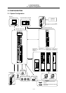
2.1 System Configuration................................................................................................ I-2
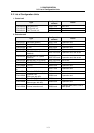
2.2 List of Configuration Units......................................................................................... I-3
3. INSTALLATION................................................................................................................. I-6
3.1 General Specification................................................................................................ I-6
3.2 General Connection Diagram.................................................................................... I-8
3.3 Countermeasures against Heat Radiation .............................................................. I-11
3.4 Noise Countermeasures ......................................................................................... I-12
3.4.1 Connection of Frame Ground (FG)................................................................ I-12
3.4.2 Shield Clamping of Cables............................................................................. I-13
3.4.3 Connection of Spark Killer ............................................................................. I-14
3.4.4 Countermeasures against Lightning Surge Protection .................................. I-15
3.5 Installation............................................................................................................... I-17
3.6 Mounting Conditions ............................................................................................... I-18
3.7 Turning the Power ON Again .................................................................................. I-19
4. CONTROL UNIT CONNECTIONS................................................................................... I-20
4.1 Names of Each Control Unit Part............................................................................ I-20
4.2 Connecting the Power Supply................................................................................. I-21
4.3 Connecting the Communication Terminal............................................................... I-22
4.4 Connecting the Synchronous Feed Encoder .......................................................... I-23
4.5 Connecting the Sensor Signal (skip)....................................................................... I-24
4.6 Connecting the Servo Drive Unit............................................................................. I-25
4.7 Connecting the Manual Pulse Generator................................................................ I-26
4.8 Connecting the Machine Control Signal.................................................................. I-27
4.9 Connecting the Remote I/O Unit ............................................................................. I-32
4.10 Connecting the RS-232C Device .......................................................................... I-34
4.11 Connecting Other Peripheral Devices................................................................... I-35
4.12 Connecting the Display Unit with Ethernet............................................................ I-38
4.13 Connecting the Network with MELSECNET/10 .................................................... I-39
4.14 Connecting the IO Device with CC-Link................................................................ I-41
4.15 Connecting the IO Device with DeviceNet ............................................................ I-43
4.16 Control Unit Connector Pin Assignments..............................................................
I-45