


3. INSTALLATION
3.5 Installation
I - 17
3.5 Installation
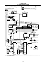
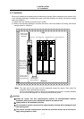
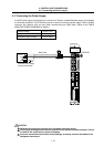
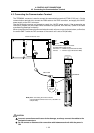
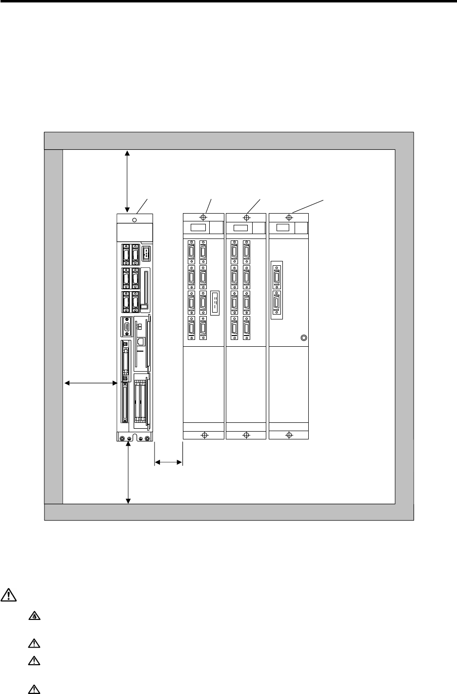
Each unit is installed in the sealed structure cabinet as a principle. When installing into the cabinet, refer
to the following drawings to consider the control unit's heat radiation and wiring, and secure enough
space for ventilation.
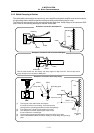
(1) Install each unit vertically so that the front is visible.
(2) Refer to the following drawings to consider the control unit's heat radiation and wiring, and secure
enough space for ventilation.
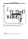
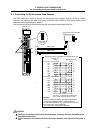
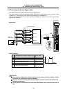
d
(Top)
(Bottom)
Servo drive unit Spindle drive unit Power supply unit Control unit
50mm or more
(heat dissipation,
wiring allowance)
*10mm or more
when there is a
unit on the left
100mm or more
(heat dissipation,
wiring allowance)
10mm or more
(heat dissipation,
wiring allowance)
MITSUBISHI
MELDAS
C64
50mm or more
(heat radiation
allowance)
(Note) The right side of the control unit will temporarily expand by approx. 2mm when the
expansion card is inserted and removed.
It will not be possible to insert or remove the expansion card if there is no space between
the control unit and adjacent unit. Always provide sufficient space.
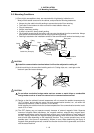
CAUTION
Install the control unit and communication terminal on noncombustible material.
Installation directly on or near combustible material may lead to fires.
Always observe the installation direction.
Do not install or operate a control unit or communication terminal that is damaged or that
has missing parts.
The control unit and communication terminal are precision devices so do not drop or
apply strong impacts on them.