


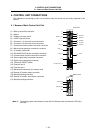
4. CONTROL UNIT CONNECTIONS
4.5 Connecting the Sensor Signal (skip)
I - 24
4.5 Connecting the Sensor Signal (skip)
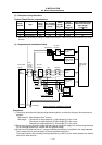
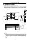
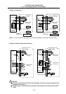
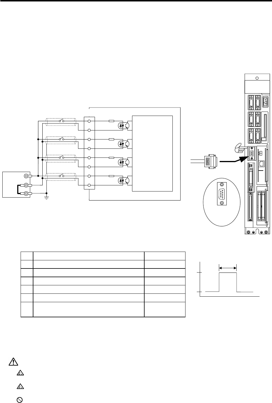
The SKIP connector is used to connect the sensor signal (skip).
The sensor signal is used for high-speed signal processing, so take special care to prevent noise
induction, etc., from occurring. If the cable is long, always use a shielded wire.
Note that the input conditions, such as the input signal holding time, differ from the machine input/output
signal's input conditions.
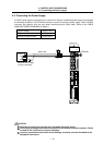
C6/C64 control unit
FG
SKIP
SKIP
Control unit
LED1
F340 cable
Input circuit
24VDC(+)
0V
FG
Stabilized
power supply
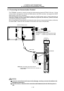
1
5
6
9
SKIP
connector
pin No.
SKIP
1
6
4
9
3
8
2
7
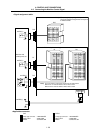
Control circuit
SKIP IN0
SKIP IN2
SKIP IN3
SKIP IN1
2.2k
Ω
2.2k
Ω
2.2k
Ω
2.2k
Ω
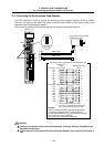
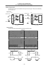
Input conditions
1 Input voltage when external contact is ON 18V or more
2 Input current when external contact is ON 9mA or more
3 Input voltage when external contact is OFF 4V or less
4 Input current when external contact is OFF 1mA or less
5 Input signal holding time (Ton) 2ms or more
6 Internal response time 0.08ms or less
7 Machine side contact capacity
30V or more,
16mA or more
+24V
GND
Ton
Ton
≥
2ms
t
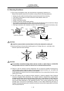
CAUTION
Do not apply a voltage other than that specified in this manual onto the connector. Failure
to observe this could lead to rupture or damage.
Incorrect connections could cause device damage, so always connect the cables to the
designated connectors.
Do not connect or disconnect the connection cable between each unit while the power is
ON.