


APPENDIX 9 EMC INSTALLATION GUIDELINES
Appendix 9.6 Parts for EMC Countermeasures
I - 114
Appendix 9.6 Parts for EMC Countermeasures
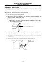
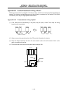
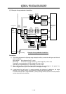
Appendix 9.6.1 Shield clamp fitting
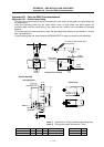
The effect can be enhanced by directly connecting the outer sheath of the cable to the grounding plate
as shown below.
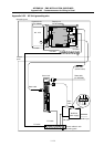
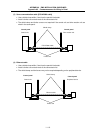
Install the grounding plate near the outlet (within 10cm) of each panel, and press against the
grounding plate with the clamp fitting. If the cables are thin, several can be bundled and clamped
together.
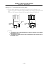
To provide sufficient frame grounding, install the grounding plate directly on the cabinet or connect
with a grounding wire.
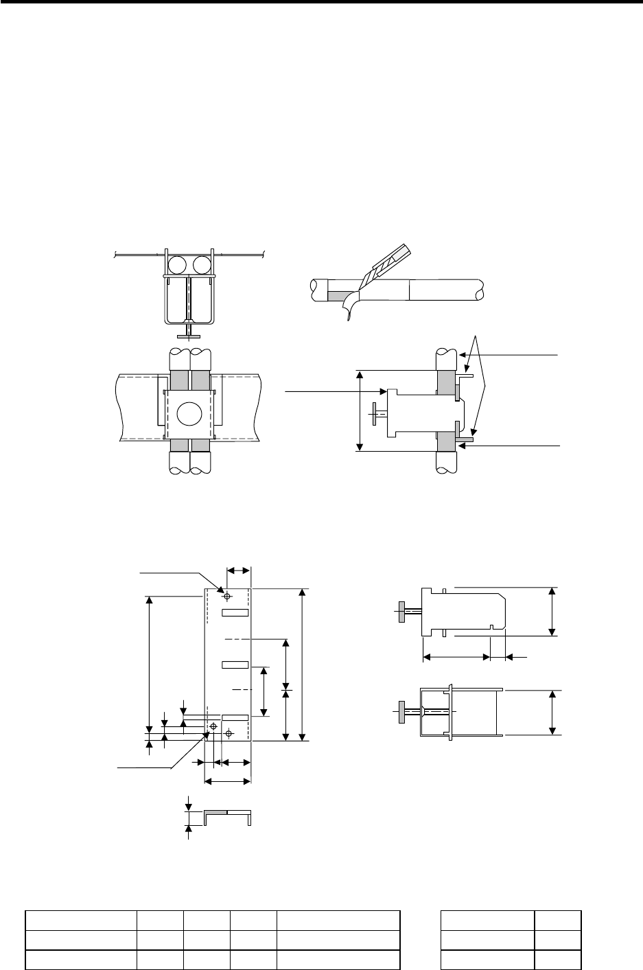
If the grounding plate and clamp fitting set AERSBAN-SET is required, please contact Mitsubishi.
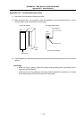
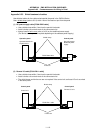
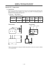
Clamp section drawing
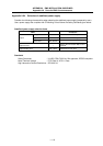
Outline drawing
Peel off the cable sheath at the
clamp section.
Grounding
plate
Cable
Shield
sheath
Clamp fitting
(Fitting A,B)
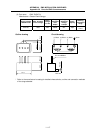
2-
φ
5 hole
Installation hole
17.5
M4 screw
Note 1)
6
22
35
10
MAX L
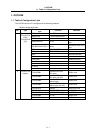
Clamp fitting
Unit: mm
A
35
C
24
-0.2
0
B±0.3
6
3
7
11
30
24
0
+0.3
Cable
40
Grounding plate
Note 1) Screw hole for wiring to cabinet's grounding plate.
Note 2) The grounding plate thickness is 1.6mm.
A B C Enclosed fitting L
AERSBAN-DSET 100 86 30 Two A clamp fittings A clamp fitting 70
AERSBAN-ESET 70 56 – One B clamp fitting B clamp fitting 45