


APPENDIX 7 CABLE MANUFACTURING DRAWINGS
Appendix 7.14 FCUA-R211 Cable Manufacturing Drawing
I - 99
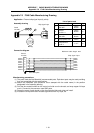
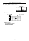
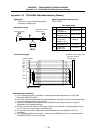
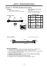
Appendix 7.14 FCUA-R211 Cable Manufacturing Drawing
Application:
Control unit – remote I/O unit connection
Remote I/O unit – remote I/O unit connection
Remote I/O unit – communication terminal connection
Option (Compatible connector set)
FCUA-CN211
(Note that when a one end connector
and contact are used, there is no
crimp terminal)
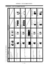
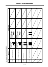
List of parts used
1
2
3
4
5
1
2
R211
X
X
R211
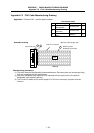
Control unit side
Note (3)
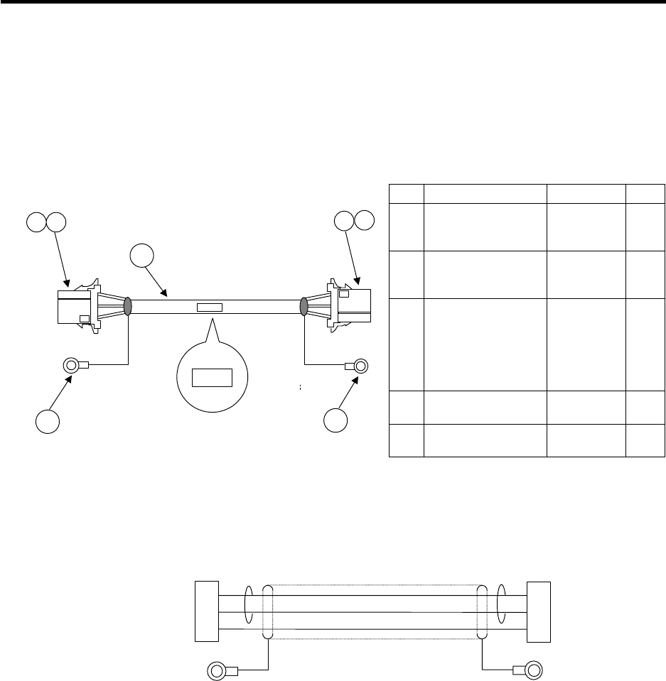
Assembly drawing
No. Part name/type Maker Qty.
1
Connector
1-178288-3
Tyco
Electronics
AMP
2
2
Contact
1-175218-2
Tyco
Electronics
AMP
6
3
Wire material
MIX3CHRV-SV-SB
Twisted pair cable
with compound
3-pair shield.
Note (1)
TOA
Electric
Industry
(1)
4
Crimp terminal
V1.25-3
J. S. T 1
5
Crimp terminal
V1.25-5
J. S. T 1
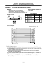
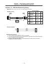
1
2
3
1
2
3
TXRX
TXRX*
LG
FG
Note (5)
TXRX
TXRX*
LG
FG
Maximum cable length: 50m
Connection diagram
Manufacturing precautions
(1) The wire material shall be a shielded 3-pair stranded pair cable equivalent to AWG20 (0.5mm
2
).
(2) The parts used shall be Mitsubishi recommended parts. Equivalent parts may be used providing
they are compatible with the specifications.
(3) Attach the nameplate (with protective cover stamped with the cable name) in the position
designated in the assembly drawing.
(4) Install each crimp terminal side after stamping the name of each signal on the mark tube.
(5) Protect both ends of the wire material with insulation bushing.
(6) Use AWG18 (0.75mm
2
) or equivalent for the shield treatment wire material.
(7) Ground the crimp terminal connected to the shield to the control unit or communication terminal
frame ground.
Note that there may be cases where only one end is connected, both ends are connected, or
neither end is connected to improve the noise resistance,.