


6. CONNECTION OF REMOTE I/O UNIT
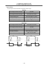
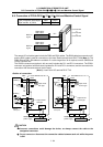
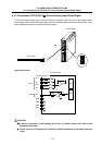
6.11 Connection of FCUA-DX12 Unit and Machine Control Signal
I
- 68
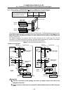
6.11 Connection of FCUA-DX12 Unit and Machine Control Signal
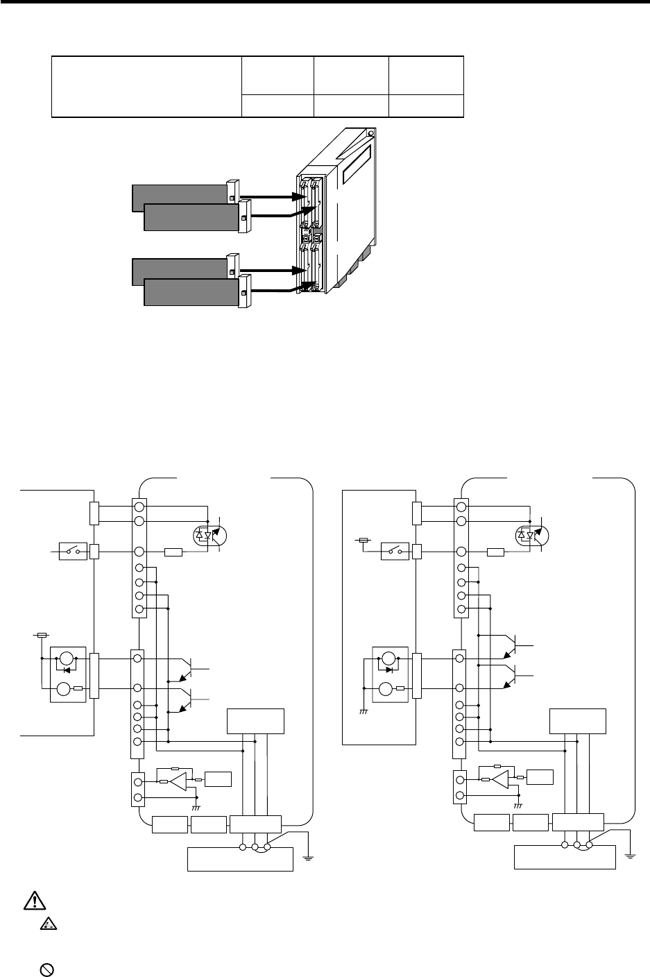
Input Output
Analog
output
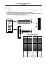
Type of machine input/output
signal and No. of points
64 points 48 points 1 point
DO-L
R300 cable/
R301 cable
DI-L
R300 cable/
R301 cable
Machine
signal
FCUA-DX12
DCIN
RIO2
RIO1
Machine
signal
DI-R
DO-R
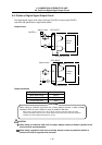
The remote I/O unit cable types include the R300 and R301 cables. The R300 cable has one end cut off,
and the R301 cable is used for connection to the Izumi Denki terminal block BX1F-T40A (Note 1). The
R300-3M and R301-3M cables are available. If a cable longer than 3m is required, use the CN300 and
CS301 connector set.
The CN300 connector set (optional, with one end) includes the DI-L (DI-R) and DO-L (DO-R)
connectors. The CS301 connector set (optional, with both ends) includes the DI-L and DO-L connectors,
and two connectors for connection with the terminal block (Izumi Denki).
(Note 1) Izumi Denki I/O terminal BX1F-T40
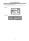
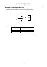
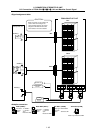
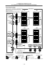
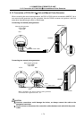
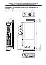
<Outline of connection>
24VDC(+)
24VDC(+)
Machine
control panel
DI-L/R
FCUA-DX120
COM
A
3
B3
B1
B2
A1
A2
B1
B2
A1
A2
2.2kΩ
Input circuit
sink type
Output circuit
sink type
DO-L/R
0V
RA
PL
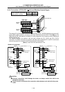
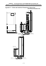
24VDC(+)
COM
A
3
B3
B1
B2
A1
A2
B1
B2
A1
A2
2.2kΩ
Input circuit
source type
Output circuit
source type
0V
RA
PL
0V
DI-L/R
DO-L/R
FCUA-DX121
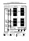
B4
A4
DAC
R
R
220Ω
DCIN
24VDC(+) 0V FG
1 2 3
RIO2 RIO1
FG
DO-R
A
nalog
output
B4
A4
DAC
R
R
220Ω
Stabilized
power supply
DCIN
24VDC(+) 0V FG
1 2 3
RIO2 RIO1
FG
DO-R
Control
circuit
Stabilized
power supply
Control
circuit
Machine
control panel
A
nalog
output
CAUTION
Incorrect connections could damage the device, so always connect the cable to the
designated connector.
Do not connect or disconnect the connection cables between each unit while the power
is ON.