


4. CONTROL UNIT CONNECTIONS
4.13 Connecting the Network with MELSECNET/10
I - 39
4.13 Connecting the Network with MELSECNET/10
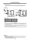
The coaxial bus type and optical loop type networks can be used between the controllers in the
MELSECNET/10 data link system. When using the coaxial bus type, the FCU6-EX878 MELSECNET/10
unit must be mounted in the control unit's extension slot, and when using the optical loop type, the
FCU6-EX879 MELSECNET/10 unit must be mounted.
This unit functions as the control station and normal station of the MELSECNET/10 data link system.
Refer to the AJ71QLP21 (S1)/AJ71QBR11 type MELSECNET/10 Network Unit User's Manual
(Hardware Section) for details on MELSECNET/10.
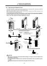
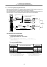
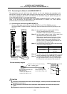
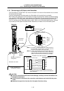
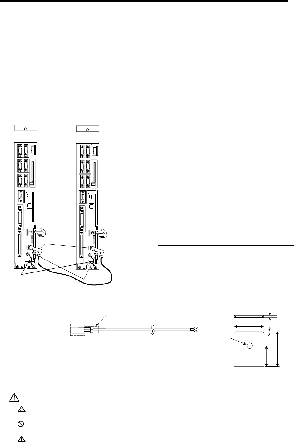
(1) Connecting the coaxial bus type MELSECNET/10
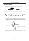
Connect a dedicated coaxial cable to the MELSECNET/10 unit (FCU6-EX878) connector.
Use the enclosed F-shape connector, and always install the terminator A6RCON (optional) on the
final unit.
Terminator
MELSEC
NET/10
Control unit
Control unit
MELSECNET/10
FG wire
(Note 5)
F-shape
connector
LED1
LED1
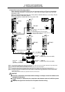
(Note 1)
Use a high-frequency coaxial cable 3C-2V or
5C-2V (compliant with JIS-C-3501).
The BNC-P-
-Ni-CAU (DDK) is recommended.
(Note 2) Lay the coaxial cable at least 100mm away from
the other drive lines and control cables.
When using in an adverse environment, or when
compliance to EMC Directives is required, use a
double shielded coaxial cable (Mitsubishi Wire
5C-2V-CCY, etc.). Connect the outer shield to the
FG using the shield clamp fitting.
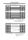
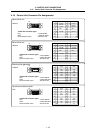
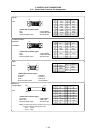
(Note 3) Use the following length of coaxial cable according
to the total number of stations.
Total number of stations Distance between stations
1 to 9 stations 1 to 500m
10 to 32 stations
1 to 5m
13 to 17m
25 to 500m
(Note 4) The BNC-TMP-05 (75) (Hirose Electric) terminator
can be used instead of the A6RCON-R75 (optional).
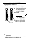
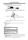
(Note 5) Connect the FG wire from the FG terminal on the
front of the MELSECNET/10 unit (FCU6-EX878) to
the FG terminal on the bottom of the control unit.
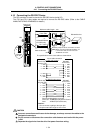
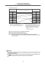
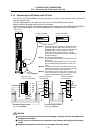
FG cable assembly diagram
Protective tube or connector housing
A
MP: 171809-2 (black)
Recommended terminal type:
A
MP 250 Series
170232-2 (for AWG 20-14)
170234-2 (for AWG 12-10)
Select according to the
terminal block being used.
Crimp terminal
φ
2
A
pplicable tab shape
0.8
±
0.025
0.9
5.0
6.2
9.6
CAUTION
Incorrect connections could cause device damage, so always connect the cables to the
designated connectors.
Do not connect or disconnect the connection cable between each unit while the power
is ON.
Separate the signal wire from the drive line/power line when wiring.