


6. CONNECTION OF REMOTE I/O UNIT
6.4 Connection of Remote I/O Power Supply
I - 58
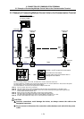
6.4 Connection of Remote I/O Power Supply
24VDC(+) is required to run the remote I/O unit. Prepare a stabilized power supply that satisfies the
following conditions.
Output voltage
24VDC±5%
Ripple
±5% (P-P)
FCUA-DX10 2.4A or more
FCUA-DX11 3.8A or more
FCUA-DX12 3.8A or more
FCUA-DX13 3.4A or more
Max. output
current
FCUA-DX14 3.4A or more
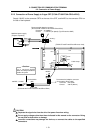
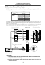
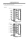
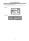
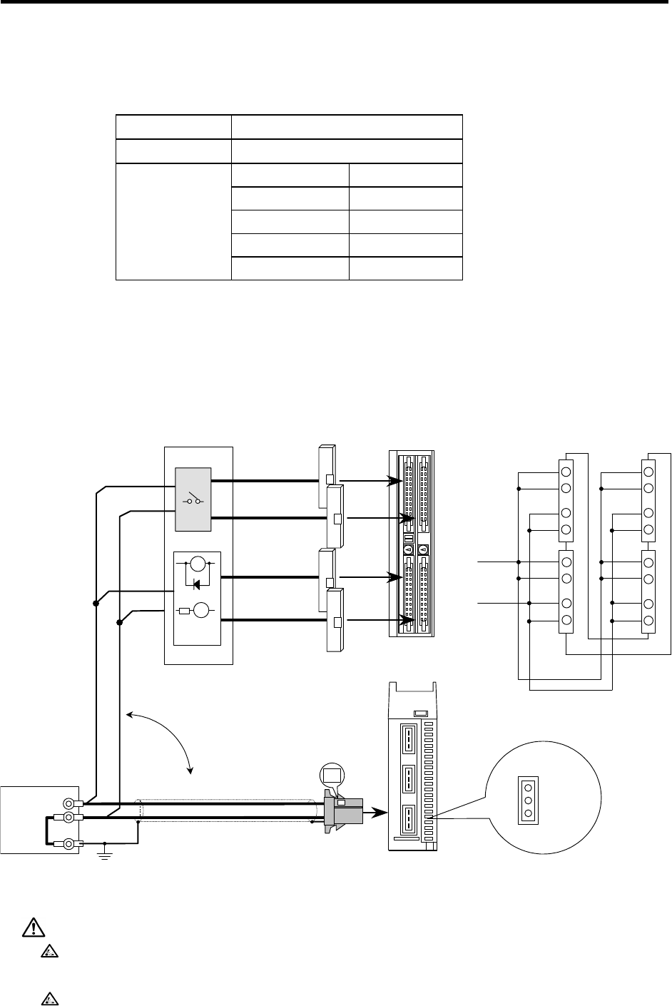
The 24VDC(+) power for the control circuit is supplied from the DCIN connector on the bottom of the unit
or from DI-L, DI-R, DO-L or DO-R connectors on the front. When supplying from the front connector,
supply to all corresponding pins.
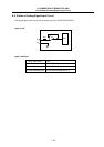
When manufacturing the R300 cable, use the CN300 one end connector (optional, with one end), and
when manufacturing the R301 cable, use the CS301 connector set (optional, with both ends).
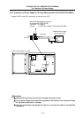
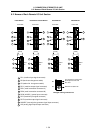
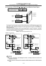
Remote I/O unit
DI-L DI-R
Machine control panel,
electric cabinet, etc.
R300 cable
or
R301 cable
Supply to either method
DI-L
<Connection outline>
Front
(Front)
(Back)
Bottom
DO-L DO-R
DI-R
DO-L DO-R
24VDC(+)
0V
DCIN
24VDC(+)
0V
FG
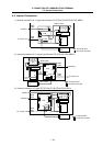
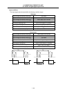
1
2
3
B1
B2
A
1
A
2
B1
B2
A
1
A
2
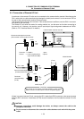
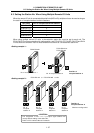
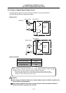
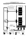
PL
RA
24VDC(+)
FG
0V
R220 cable
Stabilized power supply
(Prepare separately)
FG
Y
Y
B1
B2
A
1
A
2
B1
B2
A
1
A
2
CAUTION
Do not apply voltages other than those indicated in this manual on the connector. Doing
so may lead to destruction or damage.
Incorrect connections could damage the device, so always connect the cable to the
designated connector.