


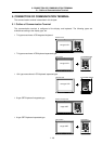
5. CONNECTION OF COMMUNICATION TERMINAL
5.4 Connection of Remote I/O Unit
I
- 53
5.4 Connection of Remote I/O Unit
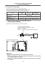
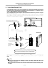
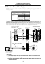
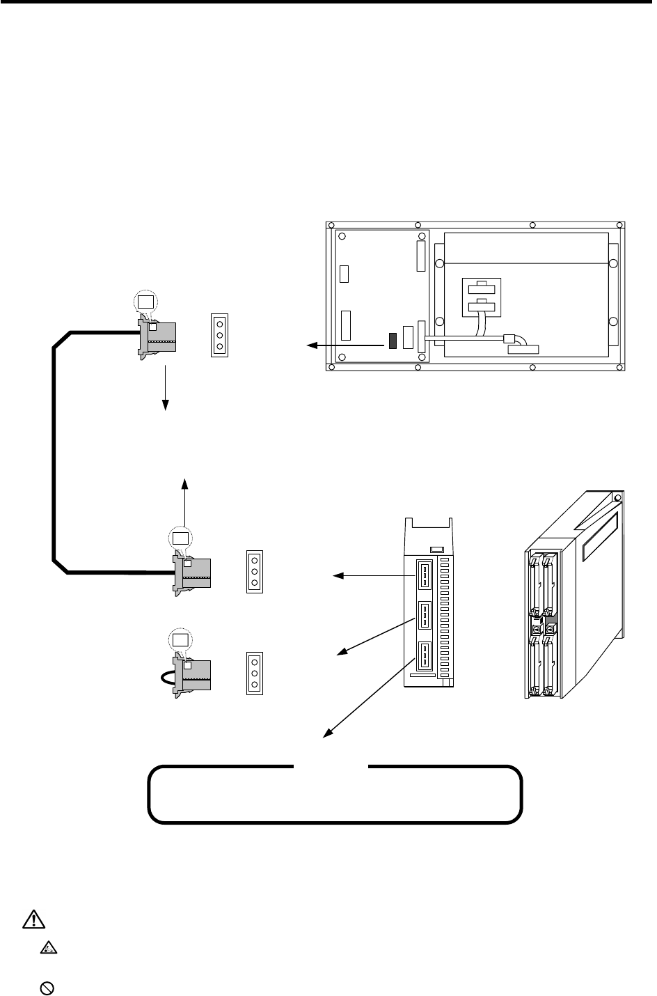
A maximum of two remote I/O units can be connected to the communication terminal. Manufacture the
R211 cable (refer to cable manufacturing drawings for details) and connect it to the connector CR5 on
the rear of the communication terminal as shown below.
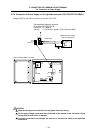
Use the enclosed connectors and contacts. If the accessories are insufficient, use the CN211 connector
set (optional, with one end).
The remote I/O unit serial link station No. setting method, etc., are the same as for when connecting to
the control unit. However, the machine control input/output signal assignment addresses will differ.
(Refer to "PLC Interface Manual" for details.)
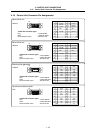
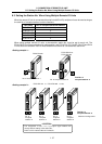
FCUA-DX1
Connector : 1-178288-3 1 piece
Contact : 1-175218-2 (gold plated) 3 pieces
(Tyco Electronics AMP)
Terminator
(sold separately)
(R-TM)
CR05
Recommended adaptive connector
(Enclosed with communication terminal)
Recommended adaptive connector
(Enclosed with FCUA-DX1
)
R211 cable
24VDC input
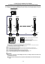
Communication terminal rear view
(Front)
(Rear)
Bottom
view
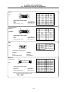
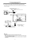
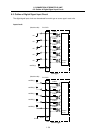
CR05
3 LG
2 TxRx*
1 TxRx
X
The remote I/O unit requires a separate 24VDC(+) power supply.
Refer to section "6.4 Connection of remote I/O power supply".
<CAUTION>
RIO1
3 LG
2 TxRx*
1 TxRx
X
RIO2
3 LG
2 TxRx*
1 TxRx
X
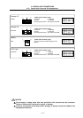
If there is a second remote I/O unit, connect the R211 cable from RIO2 connector to the second remote
I/O unit's RIO1 connector. A terminator (R-TM) must be installed on the final station's remote I/O unit’s
RIO2.
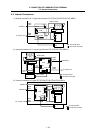
CAUTION
Incorrect connections could damage the device, so always connect the cable to the
designated connector.
Do not connect or disconnect the connection cables between each unit while the power
is ON.