


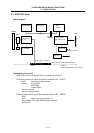
2. EXPLANATION OF MODULE FUNCTIONS
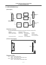
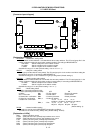
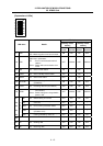
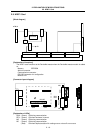
2.8 HR865 Card
II - 15
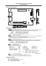
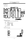
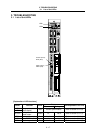
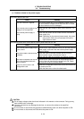
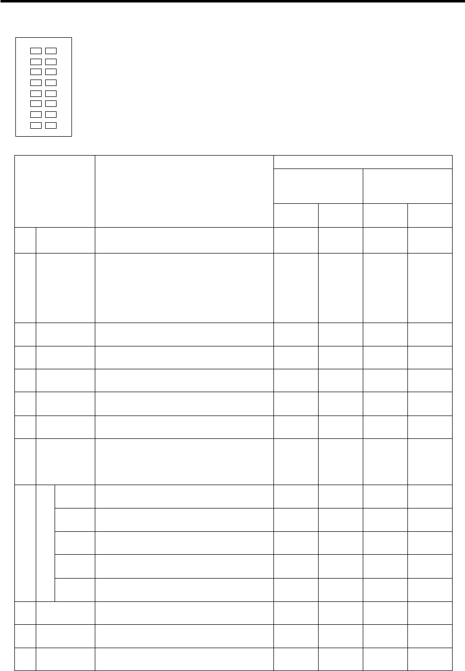
[Explanation of LEDs]
L1
L2
L3
L4
L5
L6
L7
L8
R1
R2
R3
R4
R5
R6
R7
R8
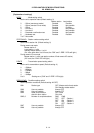
LED display status
Master station
(Standby master
station)
Local station
(Standby master
station)
LED name Details
When
normal
When
abnormal
When
normal
When
abnormal
L1 RUN
ON : Unit is normal
OFF : Watch dog timer error has occurred.
ON OFF ON OFF
L2 ERR.
Indicates the state of communication with
station set in parameters.
ON : Error in communication with all
stations
Flicker : Station with communication error
round
OFF ON/flicker OFF ON/flicker
L3 MST ON : Set as master station ON – OFF –
L4 S MST ON : Set as standby master station ON – ON –
L5 LOCAL ON : Set as local station OFF – ON –
L6 CPU R/W
ON : Communicating with NC CPU
(FROM/TO)
ON OFF ON OFF
L7 L RUN ON : Executing data link (local station) ON OFF ON OFF
L8 L ERR.
ON : Communication error
(local station)
Flicker : Switch setting was changed while
power is ON
OFF ON/flicker OFF ON/flicker
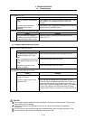
R1 SW ON : Switch setting is incorrect OFF ON OFF ON
R2 M/S
ON : A master station already exists on
same line
OFF ON – –
R3 PRM ON : Error found in parameter details OFF ON – –
R4 TIME
ON : Data link monitor timer functioned
(all-station error)
OFF ON – –
R5
E
R
R
O
R
LINE
ON : Cable is broken or transmission path
is being affected by noise, etc.
OFF ON OFF ON
R6 – – – –
R7 SD ON : Sending data ON OFF ON OFF
R8 RD ON : Receiving data ON OFF ON OFF