


2. EXPLANATION OF MODULE FUNCTIONS
2.5 HR875/876 Card
II - 8
2.5 HR875/876 Card
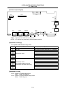
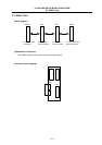
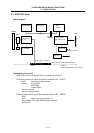
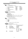
[Block diagram]
RTBUS
Connect to control
unit’s back panel
Ethernet
Controller
EEPROM
PLD
Trans-
former
PCIEXT
EXTPCI2
ETHERNET
A
dd-on
connector
Modular
j
ack
HR875
S
R
A
M
SRAM
HR876
SRAM
Physical
layer
Transceiver
Twisted
pair cable
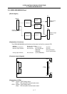
[Explanation of functions]
The HR875/876 card functions as the 10Base-T Ethernet.
□ Bus conversion section (Base PCB ... HR875)
Memory SRAM
Add-on connector
□ Ethernet interface section (Add-on PCB ... HR876)
Ethernet Controller
Physical Layer Transceiver
Transformer
Modular jack
Add-on connector
Memory SRAM
EEPROM
Monitor LED
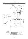
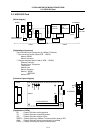
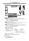
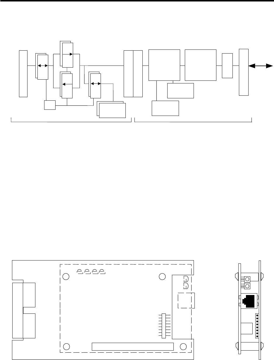
[Connector layout diagram]
COL
SPEED
LIN
K
RTBUS
FDPOL
ISP
PCIEXT/EXTPCI2
HR875
RX
TX
ETHERNE
T
HR876
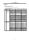
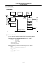
[Explanation of LEDs]
RX : (Green) ON when receiving packet
TX : (Green) ON when transmitting packet
COL : (Green) ON when collision occurs
SPEED : (Green) ON during 100Base-T communication (always OFF)
LINK : (Green) ON when mutual communication is possible
FDPOL : (Green) ON during full-duplex communication