


4. CONTROL UNIT CONNECTIONS
4.12 Connecting the Display Unit with Ethernet
I - 38
4.12 Connecting the Display Unit with Ethernet
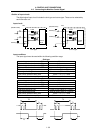
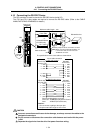
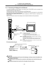
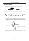
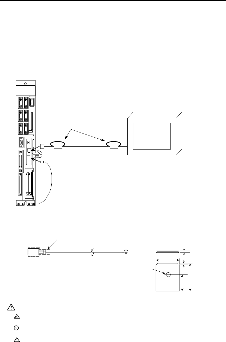
To connect the display unit with Ethernet, the Ethernet card (FCU6-EX875) must be mounted to the
extension slot EXT2 on the control unit.
Connect the Ethernet cable to the modular jack on the Ethernet card.
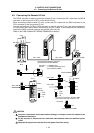
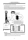
As the Ethernet cable is easily affected by noise, separate the drive line and power line, and install the
enclosed ferrite core on the control unit side.
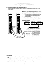
When using in an adverse environment, or when compliance to EMC Directives is required, use a
shielded cable.
Refer to the instruction manual for the display to be connected for details on other precautions.
LED1
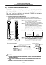
(Note 1) Install the ferrite core with the following procedure.
(1) Wind the cable once.
(2) Securely insert the case until a click is heard.
(3) Fix with constraining bands so that the position does not
deviate.
(Note 2) When using a shielded cable, a separate FG cable is required for
connecting the shield to the FG.
Normally, the cable is connected to the FG terminal on the control
unit. However, if the ground plate is closer, connect the cable
directly.
(Note 3) To comply with the EMC Directives, a ferrite core may also need to
be installed on the display side.
GOT or personal computer
Wind once
(Note 1)
Ferrite core
Ferrite core
(Note 3)
Ethernet
Ethernet FG wire
(Note 2)
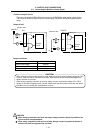
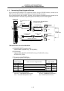
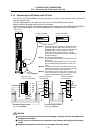
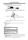
FG cable assembly diagram
Protective tube or connector housing
A
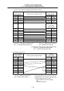
MP: 171809-2 (black)
Recommended terminal type:
A
MP 250 Series
170232-2 (for AWG 20-14)
170234-2 (for AWG 12-10)
Select according to the
terminal block being used.
Crimp terminal
Control unit
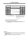
φ
2
A
pplicable tab shape
0.8
±0.025
0.9
5.0
6.2
9.6
CAUTION
Incorrect connections could cause device damage, so always connect the cables to the
designated connectors.
Do not connect or disconnect the connection cable between each unit while the power
is ON.
Separate the signal wire from the drive line/power line when wiring.