


2. EXPLANATION OF MODULE FUNCTIONS
2.4 HR881/882/883/884 Card
II - 7
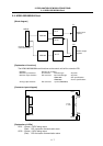
2.4 HR881/882/883/884 Card
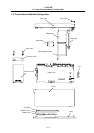
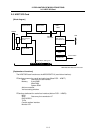
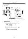
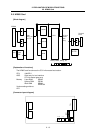
[Block diagram]
RTBUS
DI
DO
MAC303
DI I/F
DO I/F
Connect to control
unit’s back panel
MAC303
A
O I/F
Machine input
32 points
Machine output
32 points
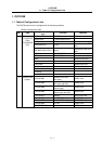
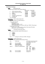
[Explanation of functions]
The HR881/882/883/884 card functions as the control unit built-in extension DIO.
MAC303 Remote I/O controller
Machine input interface DI connector Insulation type 32 points
Machine output interface DO connector Non-insulated type 32 points
HR881/882 Sink specifications
HR883/884 Source specifications
Analog output interface DO connector 1 point (HR882/884)
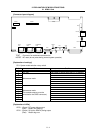
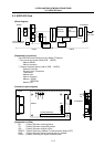
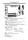
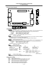
[Connector layout diagram]
LED1
U: DI
L: DO
LED2
RTBUS
[Explanation of LEDs]
LED1 : (Green) 15VDC being output
(Red) RIO 1st station communication alarm
LED2 : (Green) 15VDC being output
(Red) RIO 2nd station communication alarm