


2. EXPLANATION OF MODULE FUNCTIONS
2.1 HR851 Card
II - 4
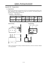
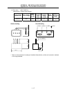
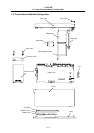
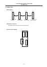
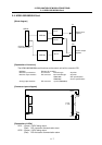
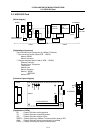
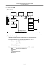
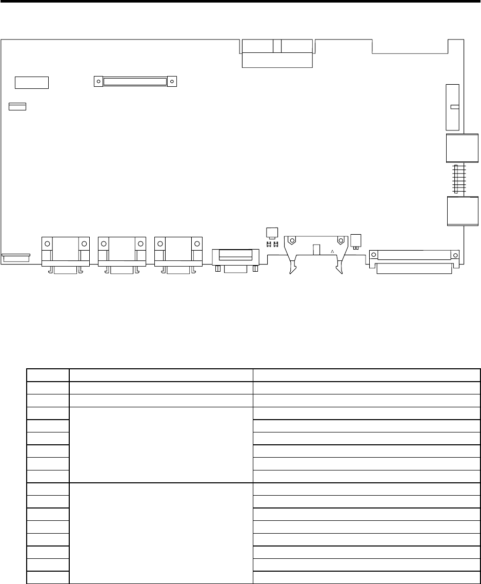
[Connector layout diagram]
FAN
CS1
ICCARD
RTBUS
DC24IN
TEST
RIO-M/S
ISP
RIO-M
CBUS
SW2
DIO
NCRST
LED3
SKIP
U:TERMINAL
L:SIO
U:HANDLE
L:ENC
U:SV2
L:SV1
LED4
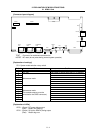
TEST : Connector for maintenance and service
NCRST : NC reset (do not press during normal system operation)
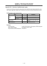
[Explanation of settings]
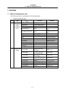
CS1: System mode selection rotary switch
Switch Mode Details
0 Standard mode Operation of system 1
1 PLC stop The system is started while the PLC is stopped.
2
3
4
5
6
7
Maintenance mode
8
9
A
B
C
D
E
F
Maintenance mode
(The cassette memory must be
connected to the CBUS connector.)
[Explanation of LEDs]
LED3 : (Green) DC power being output
(Red) Battery low warning
LED4 : (Green) SA (servo READY) being output
(Red) Watch dog error