


5. CONNECTION OF COMMUNICATION TERMINAL
5.2 Connection of Power Supply
I
- 50
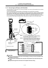
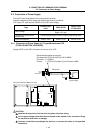
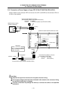
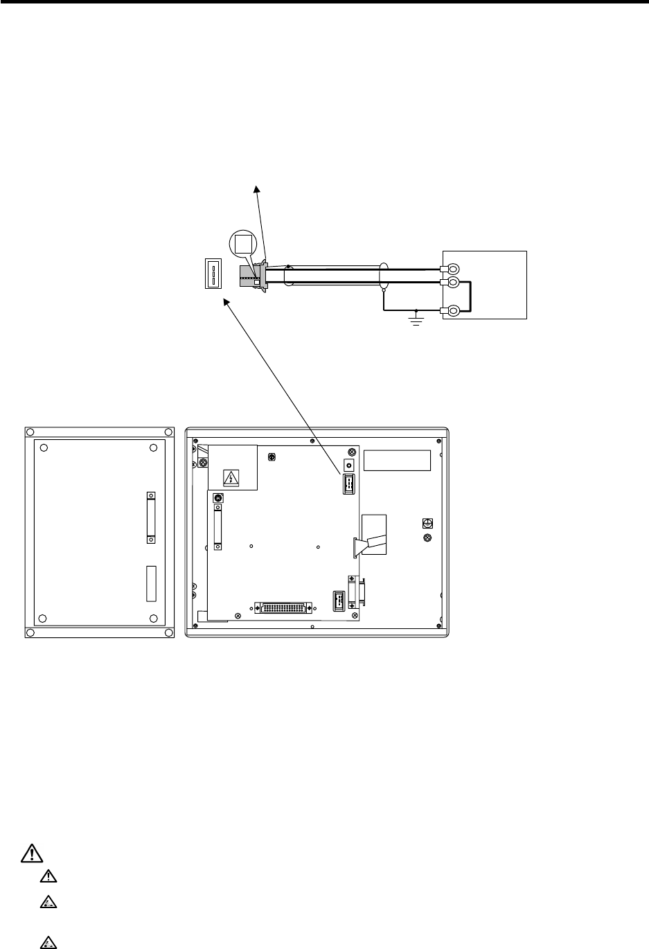
5.2.2 Connection of Power Supply to 10.4-type Monochrome LCD (FCU6-DUT32+KB021)
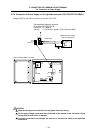
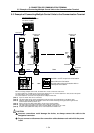
Supply 24VDC to the CR01 connector on the rear of the LCD.
FG 3
0V 2
24VDC(+) 1
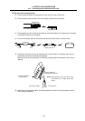
R220 cable
24VDC(+)
0V
FG
Stabilized power supply
(Prepare separately)
FG
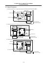
[FCU6-DUT32+KB021 rear view]
J1
J2
CR03
CR01
CN24
CR02
CR06
CR05
OPERATION BOARD Ver.A
FCU6-DUT32
MITSUBISHI ELECTRIC CORP.
Y
CAUTION
Separate the signal wire from the drive line/power line when wiring.
Do not apply voltages other than those indicated in this manual on the connector. Doing
so may lead to destruction or damage.
Incorrect connections may damage the devices, so connect the cables to the specified
connectors.
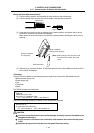
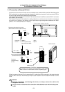
Recommended adaptive connector
(Enclosed with FCU6-DUT32)
Connector : 2-178288-3
Contact : 1-175218-5 (tin plated) (Tyco Electronics AMP)