


3. INSTALLATION
3.6 Mounting Conditions
I - 18
3.6 Mounting Conditions
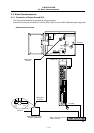
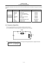
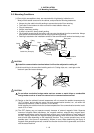
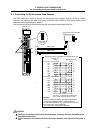
(1) Parts, highly susceptible to dust, are mounted with a high density inside the unit.
Always use a sealed structure for the cabinet, and provide the following treatments.
• Always plug the cable inlet with packing to prevent dust and oil from entering.
• Take care so that outdoor air does not enter the heat radiation holes, etc.
• Plug all clearances.
• Always install door packing.
• If there is a back lid, always install packing.
• Oil will easily accumulate at the ceiling, and can enter the cabinet from the screw holes. Always
take special countermeasures such as using oil-preventing packing.
• Packing is attached to the installation surface of the communication terminal and ready to use.
Cable
Cable inlet (Example)
Fitting
Packing
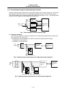
Doo
r
Display
Cabinet
Rear plate
Packing
Packing
Communication
terminal
Communication
terminal
Packing
CAUTION
Install the communication terminal where it will not be subjected to cutting oil.
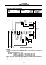
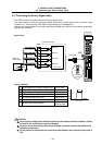
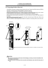
(2) Avoid machining in the area after installing each unit. Cutting chips, etc., could get on the
electronic parts and cause damage.
Display
CAUTION
Do not allow conductive foreign matter such as screws or metal chips or combustible
foreign matter such as oil enter the control unit or communication terminal.
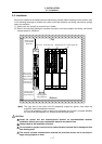
(3) Design so that the cabinet's internal temperature will not exceed the ambient temperature by
10°C or higher, and so that the control unit and communication terminal, etc., are within the
temperature conditions. (Refer to Section 4.3 for details.)
Avoid installing the cabinet where the surface temperature of the communication terminal could
reach 45°C or more.
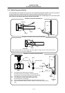
(4) The CRT display may not operate correctly because of external magnetic fields. Separate
sources of magnetic fields (transformer, fan, magnetic switcher, solenoid relay, magnet stand,
magnetized workpiece, power lines with large currents, etc.) at least 200mm or more away from
the CRT display. Note that the magnetic fields generated by these sources are each different,
and will also differ depending on the installation direction. Thus, correct operation may not be
possible even if the source is separated by 200mm or more. When determining the layout of
magnetic field generating sources, consider the direction that the field is generated, and confirm
with the actual machine.